[0007]An
advantage of the invention is that it provides a light-emitting unit
system which can efficiently set an address in a light-emitting unit with little labor and can easily check if addresses are normally set.
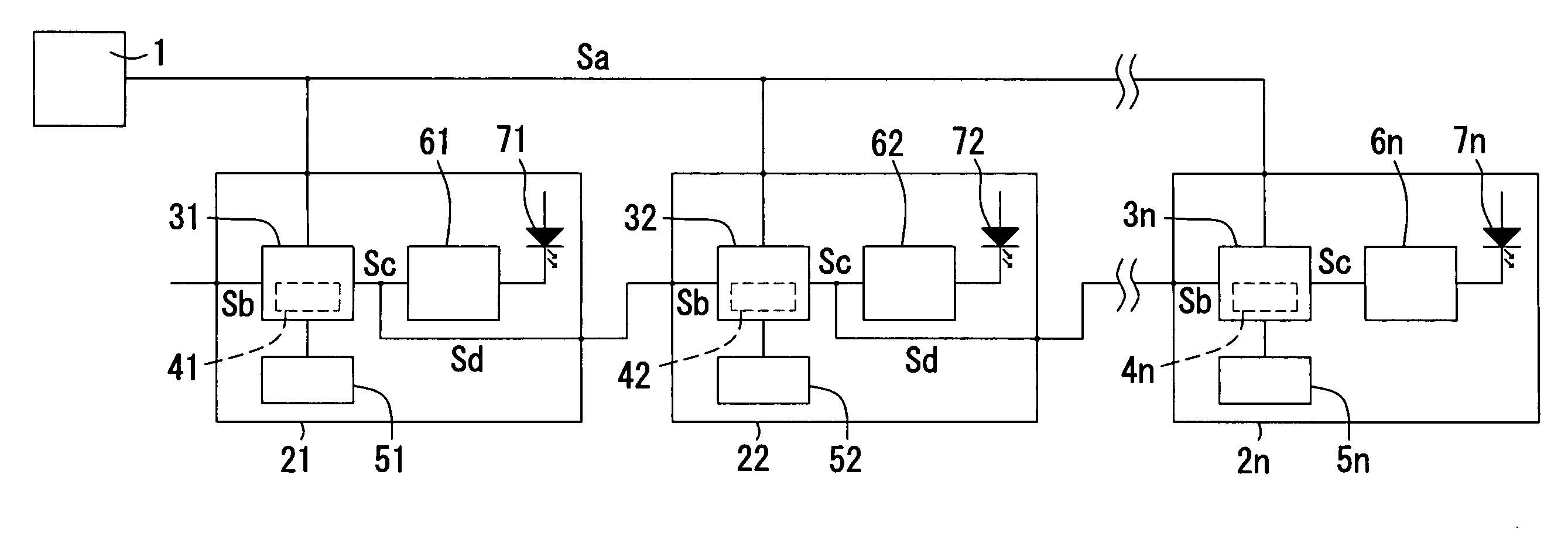
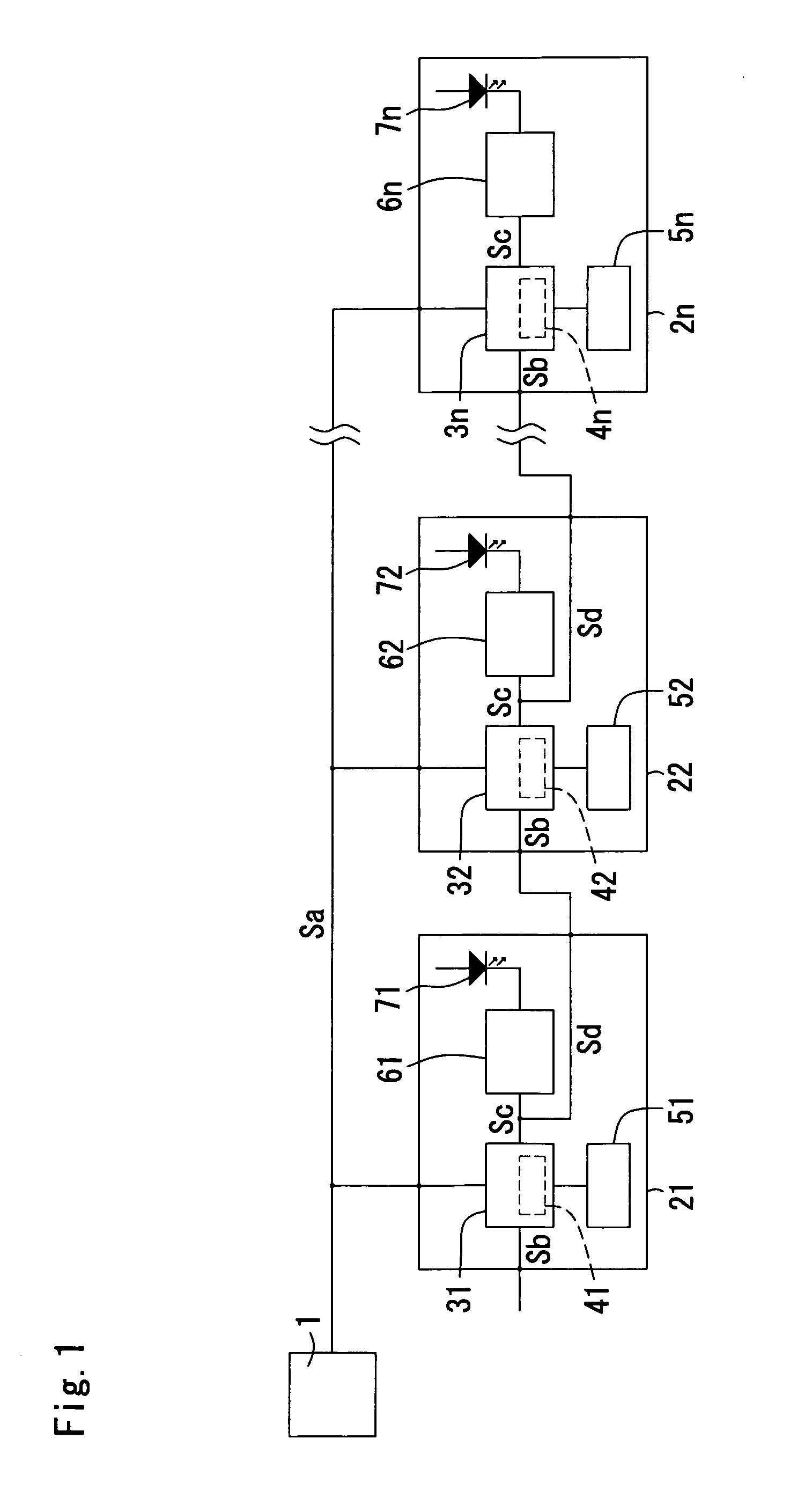
[0008]According to an aspect of the invention, there is provided a light-emitting unit
system in which respective light-emitting units having a control section, a nonvolatile memory, and a light-emitting body
driving circuit built therein are
bus-connected and
cascade-connected and which sets an address to the respective light-emitting units on the basis of a
control signal input from a
bus-connected signal line. An input-side
cascade signal line of the
first light-emitting unit is set to logic 1. On the basis of a first
control signal input from the bus-connected signal line, the control section of each light emitting unit stores a set initial address into a register and sets a signal line between the control section and the light-emitting
driving circuit and a
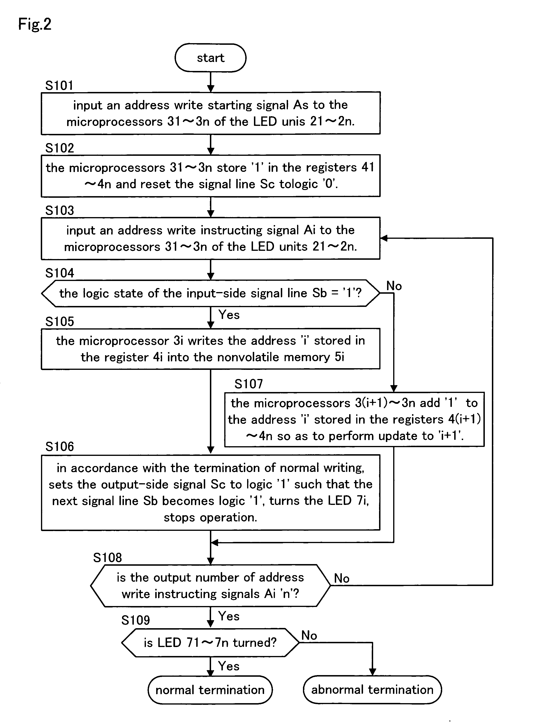
cascade signal line branched from the signal line to reach the control section of the next light-emitting unit to logic 0. On the basis of second control signals input from the bus-connected signal line which are sequentially transmitted to correspond to the address setting of the respective light-emitting units, the control section of each light-emitting unit judges the logic of the input-side cascade signal line. When the input-side cascade signal line is logic 1, the address stored in the register is written into the nonvolatile memory, the signal line between the control section and the light-emitting driving circuit is set to logic 1 so as to turn on a light-emitting body, and the cascade signal line branched from the signal line so as to reach the control section of the next light-emitting unit is set to logic 1. When the input-side cascade signal line is logic 0, the next address from the address stored in the register is obtained on the basis of a predetermined operation rule, and the address of the register is updated into the next address.
[0009]According to another aspect of the invention, there is provided a light-emitting unit system in which respective light-emitting units having a control section, a nonvolatile memory, and a light-emitting body driving circuit built therein are bus-connected and cascade-connected and which sets an address to the respective light-emitting units on the basis of a control signal input from a bus-connected signal line. An input-side cascade signal line of the
first light-emitting unit is set to logic 1. On the basis of a first control signal input from the bus-connected signal line, the control section of each light emitting unit stores a set initial address into a register and sets a signal line between the control section and the light-emitting driving circuit and a cascade signal line branched from the signal line to reach the control section of the next light-emitting unit to logic 0. On the basis of second control signals input from the bus-connected signal line which are sequentially transmitted to correspond to the address setting of the respective light-emitting units, the control section of each light-emitting unit judges the logic of the input-side cascade signal line. When the input-side cascade signal line is logic 1, the signal line between the control section and the light-emitting driving circuit is set to logic 1 so as to turn on a light-emitting body, and the cascade signal line branched from the signal line so as to reach the control section of the next light-emitting unit is set to logic 1. When the input-side cascade signal line is logic 0, the next address from the address stored in the register is obtained on the basis of a predetermined operation rule, and the address of the register is updated into the next address. On the basis of whether the counted input number of second control signals becomes the total number of light-emitting units, or on the basis of the input of a third control signal which is transmitted from the bus-connected signal line after the second control signals are output as many as the total number of light-emitting units, the respective addresses stored in the registers are written into the nonvolatile memories. When normal address setting is impossible, the signal line between the control section and the light-emitting body driving circuit is set to logic 0 so as to turn off the light emitting body.
[0010]According to a further aspect of the invention, there is provided a light-emitting unit system in which respective light-emitting units having a control section, a nonvolatile memory, and a light-emitting body driving circuit built therein are bus-connected and cascade-connected to each other and which sets an address to the respective light-emitting units on the basis of a control signal input from a bus-connected signal line. An input-side cascade signal line of the
first light-emitting unit is set to logic 1. On the basis of a first control signal input from the bus-connected signal line, the control section of each light-emitting unit sets a signal line between the control section and the light-emitting driving circuit and a cascade signal line branched from the signal line to reach a control section of the next light-emitting unit to logic 0. On the basis of second control signals and addresses input from the bus-connected signal line which are sequentially transmitted to correspond to the address setting of the respective light-emitting units and, the control section of each light-emitting unit judges the logic of the input-side cascade signal line and whether an address is not stored in a register. When the input-side cascade signal line is logic 1 and an address is not stored in the register, the input address is stored in the register and is written into the nonvolatile memory, the signal line between the control section and the light-emitting driving circuit is set to logic 1 so as to turn on a light-emitting body, and the cascade signal line branched from the signal line so as to reach the control section of the next light-emitting unit is set to logic 1.
[0011]According to a still further aspect of the invention, there is provided a light-emitting unit system in which respective light-emitting units having a control section, a nonvolatile memory, and a light-emitting body driving circuit built therein are bus-connected and cascade-connected and which sets an address to the respective light-emitting units on the basis of a control signal input from a bus-connected signal line. An input-side cascade signal line of the first light-emitting unit is set to logic 1. On the basis of a first control signal and an initial address input from the bus-connected signal line, the control section of each light emitting unit stores the input initial address into a register and sets a signal line between the control section and the light-emitting driving circuit and a cascade signal line branched from the signal line to reach a control section of the next light-emitting unit to logic 0. On the basis of second control signals input from the bus-connected signal line which are sequentially transmitted to correspond to the address setting of the respective light-emitting units, the control section of each light-emitting unit judges the logic of the input-side cascade signal line. When the input-side cascade signal line is logic 1, the signal line between the control section and the light-emitting driving circuit is set to logic 1 so as to turn on the light-emitting body, and the cascade signal line branched from the signal line to reach the control section of the next light-emitting unit is set to logic 1. When the input-side cascade signal line is set to logic 0, the next address from the address stored in the register is obtained on the basis of a predetermined operation rule, and the address of the register is updated into the next address. On the basis of whether the counted input number of the second control signals becomes the total number of light-emitting units, or on the basis of the input of a third control signal which is transmitted from the bus-connected signal line after the second control signals are output as many as the total number of light-emitting units, the respective addresses stored in the registers are written into the nonvolatile memories. When normal address setting is impossible, the signal line between the control section and the light-emitting body driving circuit is set to logic 0 so as to turn off the light emitting body.
[0012]In the invention, the construction of another embodiment may be added, the construction of each embodiment may be modified, and the construction of each embodiment may be partially removed within a predetermined limit. Further, as the light-emitting body, a suitable light-emitting body other than the LED can be used.

