Generating a Depth Map Based on a Single Image

a single image and depth map technology, applied in the field of digital image processing, can solve the problems of difficult to achieve the effect of generating a single image, requiring special hardware, and severely restricting the creation of depth maps,

Active Publication Date: 2013-05-23
ADOBE SYST INC
View PDF5 Cites 40 Cited by
  • Summary
  • Abstract
  • Description
  • Claims
  • Application Information

AI Technical Summary

Benefits of technology

[0013]Absolute positioning may be achieved via a depth tool, e.g., a “depth brush”, which may fix the depth value of pixels along the brush stroke, where the fixed value can be set by the user. This tool may effectively set Dirichlet boundary conditions inside the solution domain. Alternatively, or additionally, the depth brush may increment or decrement depth values by some specified amount.
[0014]The one or more tools may include a scissors tool that may operate to “cut” the pixel grid by decreasing neighborhood weights along the stroke. This may control, e.g., restrict, diffusion of depth values between pixels, and may be useful for separating foreground objects from the background.
[0015]The one or more tools may include a blur (or erase) tool that may operate to remove any constraints currently specified for affected areas. This tool may thus allow the user to erase inappropriate constraints.
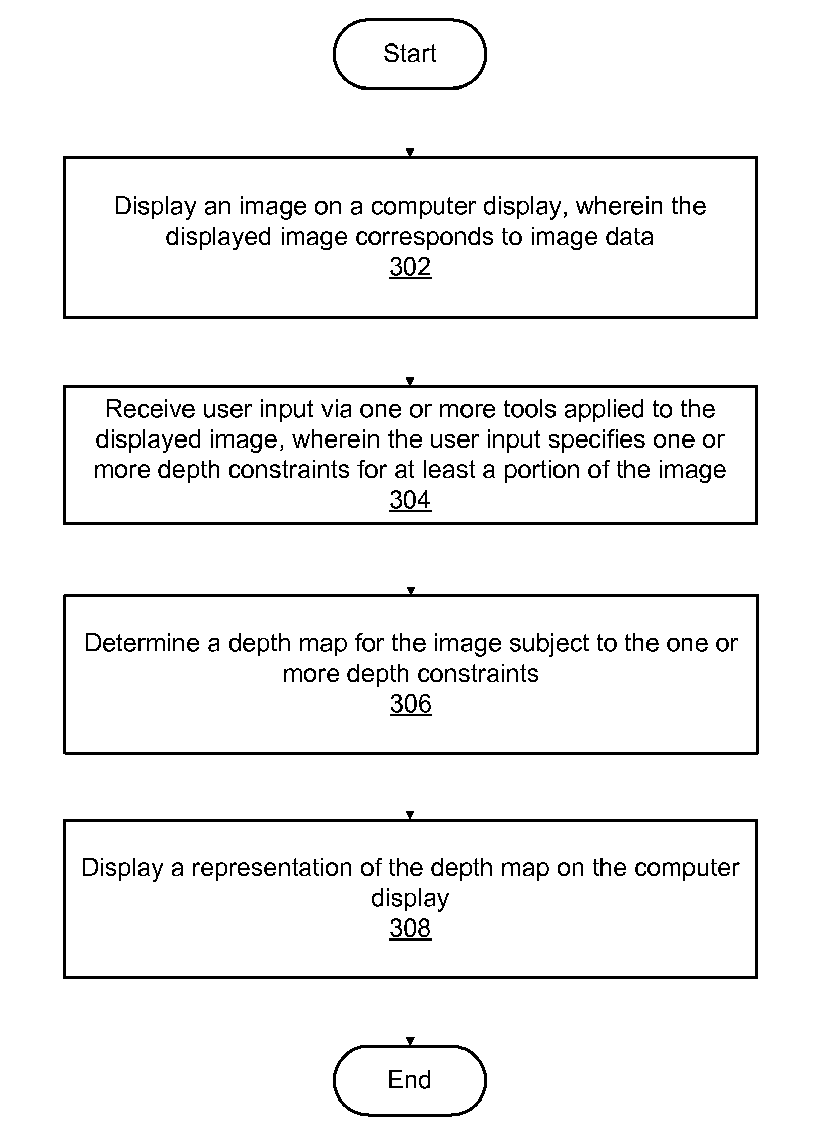
[0021]A representation of the depth map may be displayed on the computer display, e.g., in a graphical user interface (GUI). In various embodiments, the representation of the depth map may assume any of various forms. For example, in one embodiment, the representation of the depth map may include an overlay of the image, such that both the image and depth information (i.e., the representation of the depth map) are visible to the user. In one embodiment, displaying the image and displaying the representation of the depth map may be performed via such an overlay. Note further that the depth information (the representation of the depth map) may be presented in any of a variety of ways, e.g., as a 3D surface, or as a contour map, among others. Moreover, any type of 3D display technology may be used as desired, including, for example, but not limited to, red-blue stereoscopic display, polarized stereo display, autostereoscopic display, and eye tracking 3D display, among others. In another embodiment, the image and the representation of the depth map may be displayed separately, e.g., side by side, or the user may switch or flip between them. For example, the representation of the depth map may be or include a grayscale image wherein depth values are mapped to luminance values in the grayscale image. However, the overlay approaches may present a more intuitive user interface. Note that in embodiments where the representation of the depth map is a 3D surface with the image overlaid thereon, the user may need to adjust the view angle, i.e., the “camera angle” so that the image plane is not orthogonal to the view axis, so that the depth information (the 3D surface) is apparent, since the 3D surface aspects are not visible when viewed orthogonally. Thus, in some embodiments, the GUI may include controls whereby the user may modify or specify viewing parameters of the representation of the depth map, such as, for example, controls for 3D rotations of the representation, zooming, and panning, among others. In some embodiments, the GUI may also facilitate various filtering functions, whereby the user may (possibly temporarily) modify various aspects of the image, e.g., coloration, to simplify analysis and specification of depth constraints. Similarly, the user may also be allowed to specify various filters or image effects with respect to the representation of the depth map (or other representations, as discussed below).

Problems solved by technology

Automatic creation of depth maps from images often requires special hardware, multiple images of a single scene, or is severely restricted in the types of scenes that can be handled.
However, modeling 3D geometry is a laborious task that requires inferring significant amounts of scene content that may not be visible, or even physically possible (e.g. in the case of a painting with errors in perspective).
Prior art approaches to taking user's sparse input and creating dense, smooth depth values over an entire image have generally required powerful and expensive tools.

Method used


Image

  • Generating a Depth Map Based on a Single Image
  • Generating a Depth Map Based on a Single Image
  • Generating a Depth Map Based on a Single Image

Examples


examples

[0070]FIGS. 4-10 illustrate exemplary screenshots demonstrating various aspects of the present invention, according to one embodiment. Note that the figures and the effects illustrates are intended to be exemplary only, and are not intended to limit the types of images, tools, effects, or GUI to any particular form, function, or appearance.

[0071]FIG. 4 illustrates an exemplary graphical user interface (GUI) displaying an initial image, in this case, a man's face. As may be seen, in this embodiment of the GUI, various depth map tools may be invoked via a tool selection portion of the GUI, seen to the right of the displayed face. Note that in this embodiment, the tools include depth, edge, hill, valley, blur, detail, and scissors tools (e.g., image brushes), described above, although it should be noted that other tools may be implemented as desired. As also shown, this GUI also include a tool configuration section (bottom right) that includes various controls for configuring parameter...


PUM


Abstract

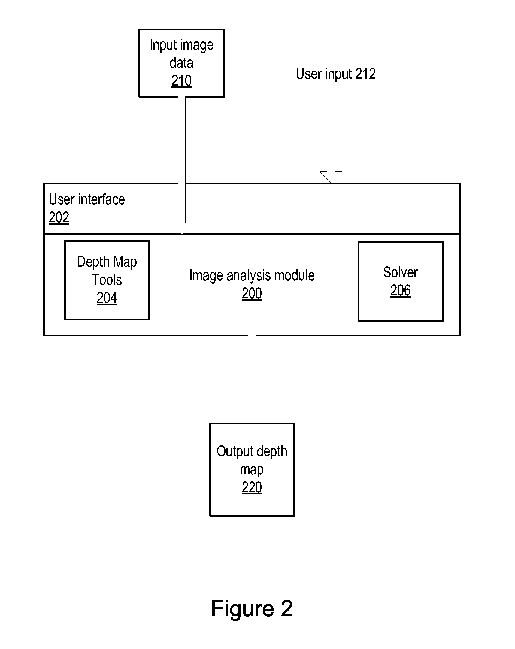
A method, system, and computer-readable storage medium for determining a depth map from a single image. An image is displayed on a computer display, where the displayed image corresponds to image data. User input via is received via one or more tools applied to the displayed image, where the user input specifies one or more depth constraints for at least a portion of the image. A depth map for the image data is automatically determined subject to the one or more depth constraints, and a representation of the depth map is displayed on the computer display

Description

PRIORITY DATA[0001]This application claims benefit of priority to U.S. Provisional Application Ser. No. 61 / 097,388 titled “Generating a Depth Map Based on a Single Image Automatic Video Image Segmentation”, filed Sep. 16, 2008, whose inventors are Stephen Diverdi and Jonathan D. Ventura, and which is hereby incorporated by reference in its entirety.BACKGROUND[0002]1. Field of the Invention[0003]The present invention is directed generally to digital image processing, and more particularly to generation of a depth map from a single image.[0004]2. Description of the Related Art[0005]Digital images may include raster graphics, vector graphics, or a combination thereof. Raster graphics data (also referred to herein as bitmaps) may be stored and manipulated as a grid of individual picture elements called pixels. A bitmap may be characterized by its width and height in pixels and also by the number of bits per pixel. Commonly, a color bitmap defined in the RGB (red, green blue) color space...

Claims


Application Information

Patent Timeline
Patent Type & Authority Applications(United States)
IPC IPC(8): G06T15/00
CPCG06T17/10G06T15/205
Inventor DIVERDI, STEPHEN J.VENTURA, JONATHAN D.
Owner ADOBE SYST INC
Why Eureka
Try Eureka