Image processing apparatus and method thereof

a technology of image processing and apparatus, applied in the field of image processing, can solve the problems of color saturation, color saturation, and chroma gain reduction, and achieve the effect of reducing the loss of details due to the chroma shift of an image toward the high-chroma side, and reducing the color saturation in chroma correction

Inactive Publication Date: 2008-03-20
CANON KK
View PDF9 Cites 15 Cited by
  • Summary
  • Abstract
  • Description
  • Claims
  • Application Information

AI Technical Summary

Benefits of technology

[0012]According to the aspect, color saturation in chroma correction can be reduced. Also, loss of details due to the chroma shift of an image toward the high-chroma side can be reduced. Furthermore, chroma correction can be executed in consideration of the relationship between the input and output gamuts.

Problems solved by technology

However, since the technique of Japanese Patent No. 2698493 detects only a chroma component of an input signal but does not detect any luminance component, it may cause color saturation due to chroma emphasis. FIG. 1 is a graph for explaining this color saturation problem; the abscissa plots the chroma level of an input signal, and the ordinate plots the luminance level of the input signal.
However, the technique of Japanese Patent No. 2698493 does not lower the chroma gain for colors which belong to areas 2 and 3 which do not include any high chroma levels.
Then, the signal values of colors which deviate from the gamut of an input signal as a result of chroma emphasis are limited to the gamut boundaries, thus causing color saturation.
Since this chroma emphasis processing is applied for each pixel, the chroma levels of the entire image shift to the vicinity of the gamut boundaries, and details of colors near the gamut boundaries may be lost.
Since the techniques of both Japanese Patent No. 2698493 and Japanese Patent Laid-Open No. 2001-346222 control chroma emphasis regardless of the gamut of a display apparatus, they suppress the chroma emphasis strength of even colors displayable due to a broad gamut of the display apparatus, and cannot obtain a chroma correction result desirable to the user.

Method used


Image

  • Image processing apparatus and method thereof
  • Image processing apparatus and method thereof
  • Image processing apparatus and method thereof

Examples


first embodiment

[Arrangement of Apparatus]

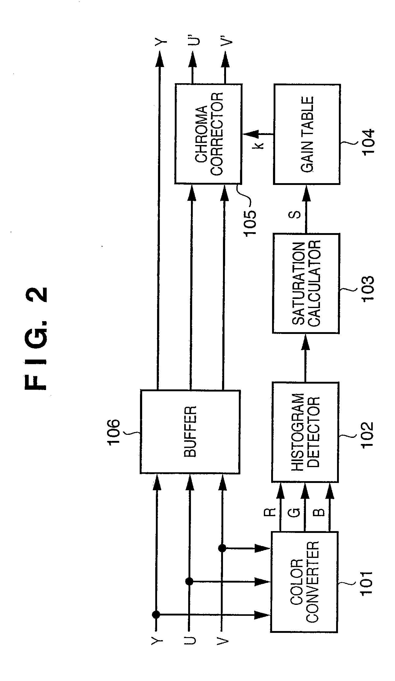
[0040]FIG. 2 is a block diagram showing the arrangement of an image processing apparatus according to this embodiment. In the first embodiment, assume that YUV signals are adopted as input signals.

[0041]A color converter 101 converts input YUV signals into RGB signals. As this conversion, for example, 3×3 matrix operations can be made. A histogram detector 102 receives the RGB signals and generates a 2D histogram. A saturation calculator 103 receives the 2D histogram, and calculates an ease of saturation S based on the 2D histogram. A gain table 104 receives the ease of saturation S and outputs a chroma gain k corresponding to the ease of saturation S. A chroma corrector 105 applies chroma correction to color-difference signals U and V output from a buffer 106 using the chroma gain k, and outputs signals U′ and V′.

[0042][Histogram Detector]

[0043]FIG. 3 is a block diagram showing the arrangement of the histogram detector 102.

[0044]A maximum-minimum detector ...

second embodiment

[0066]An image processing apparatus according to the second embodiment of the present invention will be described hereinafter. Note that the same reference numerals in the second embodiment denote the same components as in the first embodiment, and a detailed description thereof will not be given.

[0067]The image processing apparatus according to the second embodiment receives RGB signals, and applies chroma correction to the RGB signals. FIG. 8 is a block diagram showing the arrangement of the image processing apparatus of the second embodiment. The differences between the image processing apparatus of the second embodiment and that of the first embodiment are the conversion characteristics of the gain table 104, and the arrangement of a chroma corrector 107.

[0068]FIG. 9 is a block diagram showing the arrangement of the chroma corrector 107.

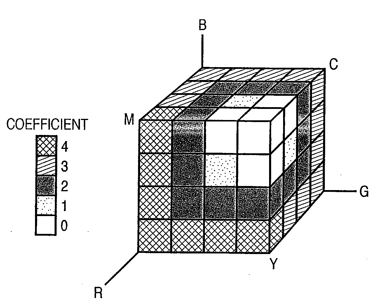
[0069]FIG. 10 shows a table which is stored in a ROM 43 and corresponds to an RGB color space divided into 5×5×5. That is, the ROM 43 stores out...

third embodiment

[0081]Image processing according to the third embodiment of the present invention will be described hereinafter. Note that the same reference numerals in the third embodiment denote the same components as those in the first and second embodiments, and a detailed description thereof will not be repeated.

[0082]The third embodiment will explain an example in which chroma correction is applied in consideration of the gamut of an image output device such as a display device or the like. FIG. 13 is a block diagram showing the arrangement of an image processing apparatus according to the third embodiment. Differences from the arrangement of the second embodiment are a histogram detector 109 and gamut corrector 108.

[0083]FIG. 14 is a block diagram showing the arrangement of the histogram detector 109.

[0084]A signal value detector 13 outputs a color component signal indicating a maximum value Max and that indicating a minimum value Min for each pixel from the input RGB signals. Also, the det...


PUM


Abstract

Color saturation in chroma correction is reduced. Hence, a two-dimensional histogram is generated in association with the luminance and chroma levels of an image for one frame. An ease of saturation of the image is calculated from the two-dimensional histogram. A chroma gain is set according to the ease of saturation. Color-difference signals undergo chroma correction according to the chroma gain k.

Description

BACKGROUND OF THE INVENTION[0001]1. Field of the Invention[0002]The present invention relates to image processing for chroma-correcting an image.[0003]2. Description of the Related Art[0004]As a scheme for automatically adjusting a chroma level, a technique for changing a chroma gain designated by the user in accordance with the chroma level of an input image is available. This technique detects the chroma level of the input image for one frame, and executes processing for decreasing the user-designated chroma gain if the chroma level is high (for example, Japanese Patent No. 2698493).[0005]However, since the technique of Japanese Patent No. 2698493 detects only a chroma component of an input signal but does not detect any luminance component, it may cause color saturation due to chroma emphasis. FIG. 1 is a graph for explaining this color saturation problem; the abscissa plots the chroma level of an input signal, and the ordinate plots the luminance level of the input signal.[0006]...

Claims


Application Information

Patent Timeline
Patent Type & Authority Applications(United States)
IPC IPC(8): H04N5/14
CPCH04N9/68
Inventor KANAI, IZUMI
Owner CANON KK
Why Eureka
Try Eureka