Zoom lens

Active Publication Date: 2008-03-20
ASIA OPTICAL INT LTD
View PDF9 Cites 3 Cited by
  • Summary
  • Abstract
  • Description
  • Claims
  • Application Information

AI Technical Summary

Benefits of technology

[0008]An objective of the present invention is to provide a periscope-type zoom lens, which is a compact optical system with high magnification and also features good imaging performance and short opening time.
[0016]The zoom lens in accordance with the present invention has a plurality of moveable lens groups, which effectively decrease the moving distance of each lens group. Thus, the size of the zoom lens can be greatly miniaturized. Also, the design of the present invention can ensure the optimum imaging performance at any of the focal points thereof as zoomed. Therefore, the zoom lens of the present invention has the advantages of high magnification and good imaging performance.

Problems solved by technology

The optical zooming is different from digital zooming whose imaging quality will be adversely affected when the focal length of photography is changed.
Although this known zoom lens is relatively compact, it dos not provide a high magnification.
However, the distance required by such a telescopic lens to zoom is inevitably quite long if it aims to acquire a high magnification.
Thus, the requirement of the miniaturization cannot be fully met.

Method used


Image

  • Zoom lens
  • Zoom lens
  • Zoom lens

Examples


first embodiment

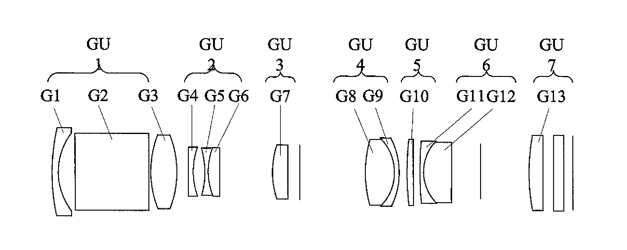
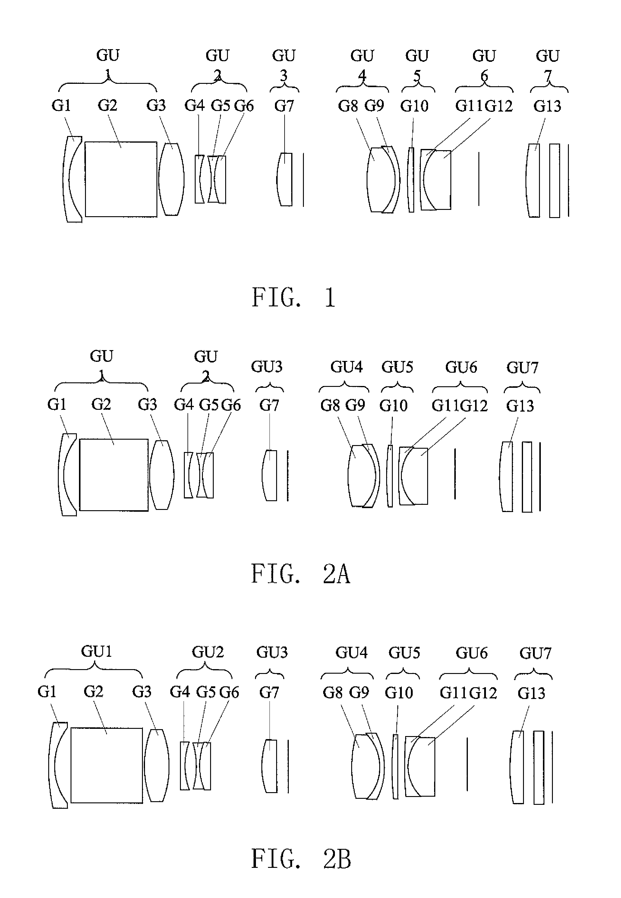
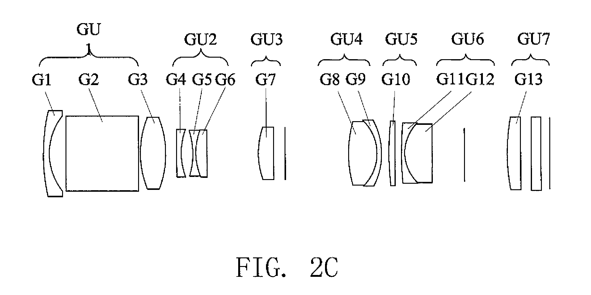
[0041]Table 1 gives parameters of the lenses comprised of the present invention. In the table, Nd represents refractive index and Vd represents Abbe-number. It is noted in Table 1 that “LPF” indicates a low pass filter having opposite planar surfaces; “IMA” is an image plane; and “Ref Plane 1” and “Ref Plane 2”, which denotes reference planes 1 and 2, are two imaginary fixed surfaces. It is also noted that “distance between lens surfaces” indicates the distance between the surface of the associated row and the surface of the next row. For example, for surface 1, the distance between lens surfaces means the distance between surfaces 1 and 2 of the table. Also, lens G5 and G6 are cemented together, so that lens G5 is shown having only one surface in Table 1, for the other surface of lens G5 is exactly coincident with one surface of the lens G6. This is also applicable to lens pairs of G8, G9 and G11, G12.

TABLE 1CurvatureDistance betweenSurfaceLensradiuslens surfacesNdVd 1G132.200.621....

second embodiment

[0046]In the present invention, the aspheric surface of the lens G8 of the fourth lens group GU4 is the first surface of the fourth lens group GU4 arranged in the direction from the object side to the image side thereof, namely the surface closest to or facing the object side. The lens G10 of the fifth lens group GU5 has two aspheric surfaces. The sixth lens group GU6 has two lenses G11 and G12, while the seventh lens group GU7 has a lens G13.

[0047]Table 4 gives parameters of the lenses comprised of the second embodiment of the present invention. In the table, Nd represents refractive index and Vd represents Abbe-number. Again, in Table 4, “LPF” indicates a low pass filter having opposite planar surfaces and “IMA” is an image plane. It is also noted that in Table 4, “distance between lens surfaces” indicates the distance between the surface of the associated row and the surface of the next row. For example, for surface 1, the distance between lens surfaces means the distance between...


PUM


Abstract

Disclosed is a zoom lens, which includes, in sequence from an object side to an image side, a positive first lens group, a negative second lens group, a positive third lens group, a positive fourth lens group, a fifth lens group, a negative sixth lens group and a positive lens group. The first, third, fifth and seventh lens groups are fixed. When the zoom lens is made to zoom from a wide-angle end to a telephoto end, the second and fourth lens groups move toward the third lens group, while the sixth lens group moves toward the seventh lens group. The absolute value of the ratio of the focal distance of the second lens group to that of the sixth lens group is within a range between 0.1 and 0.5.

Description

FIELD OF THE INVENTION[0001]The present invention generally relates to a zoom lens, and especially a compact periscope-type zoom lens having high magnification and excellent imaging performance.BACKGROUND OF THE INVENTION[0002]In order to realize convenient photography operation, various digital cameras adopt optical zoom lens. The optical zoom lens can effectively change the focal length of photography while maintains a good imaging quality thereof. The optical zooming is different from digital zooming whose imaging quality will be adversely affected when the focal length of photography is changed.[0003]US Patent Application No. US2005 / 0099700A1 discloses a compact zoom lens comprising four lens groups with positive, negative, positive and positive refraction powers, respectively. When the zoom lens is zoomed from a wide-angle end to a telephoto end, the first and third lens groups remain fixed, while the second lens group moves toward an image side thereof. Although this known zoo...

Claims


Application Information

Patent Timeline
IPC IPC(8): G02B15/14
CPCG02B15/177G02B15/173G02B15/1461
Inventor CHEN, MING-CHUNG
Owner ASIA OPTICAL INT LTD
Why Eureka
Try Eureka