
Near Field Optical Head and Information Recording and Reproducing Device

Inactive Publication Date: 2011-01-13
SEIKO INSTR INC
View PDF5 Cites 7 Cited by
  • Summary
  • Abstract
  • Description
  • Claims
  • Application Information

AI Technical Summary

Benefits of technology

[0013]In view of the above, an object of the invention is to provide a near field optical head and information recording and reproducing device, which are capable of miniaturization in size and generation of near field light with high resolution.

Problems solved by technology

Accordingly, occurs a problem of heat demagnetization such as reversal and disappearance of recorded information due to thermal fluctuation and the like.
In this system, however, easily occurs the above-mentioned disappearance of recorded information and such due to heat demagnetization.
This makes record of information in a recording medium difficult even in the case of the above-mentioned perpendicular recording system.

Method used


Image

  • Near Field Optical Head and Information Recording and Reproducing Device
  • Near Field Optical Head and Information Recording and Reproducing Device
  • Near Field Optical Head and Information Recording and Reproducing Device

Examples


first embodiment

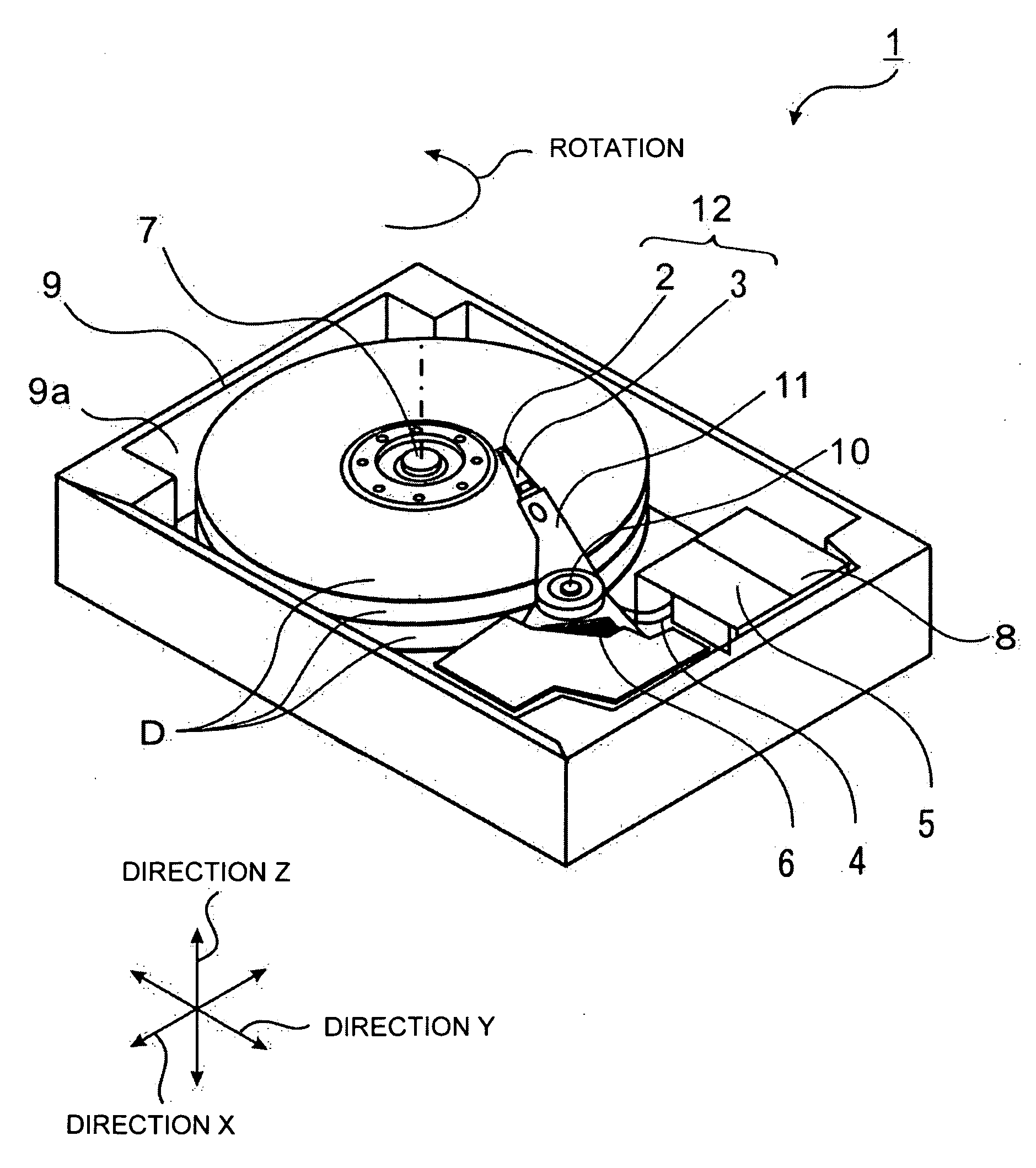
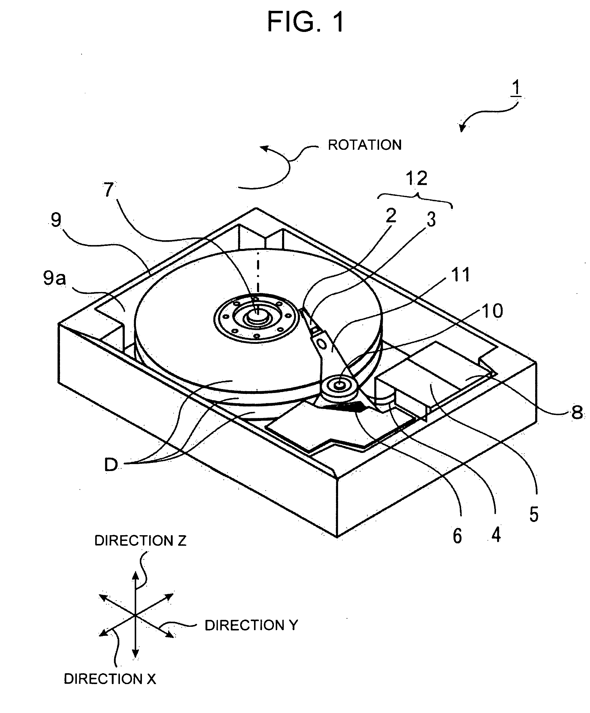
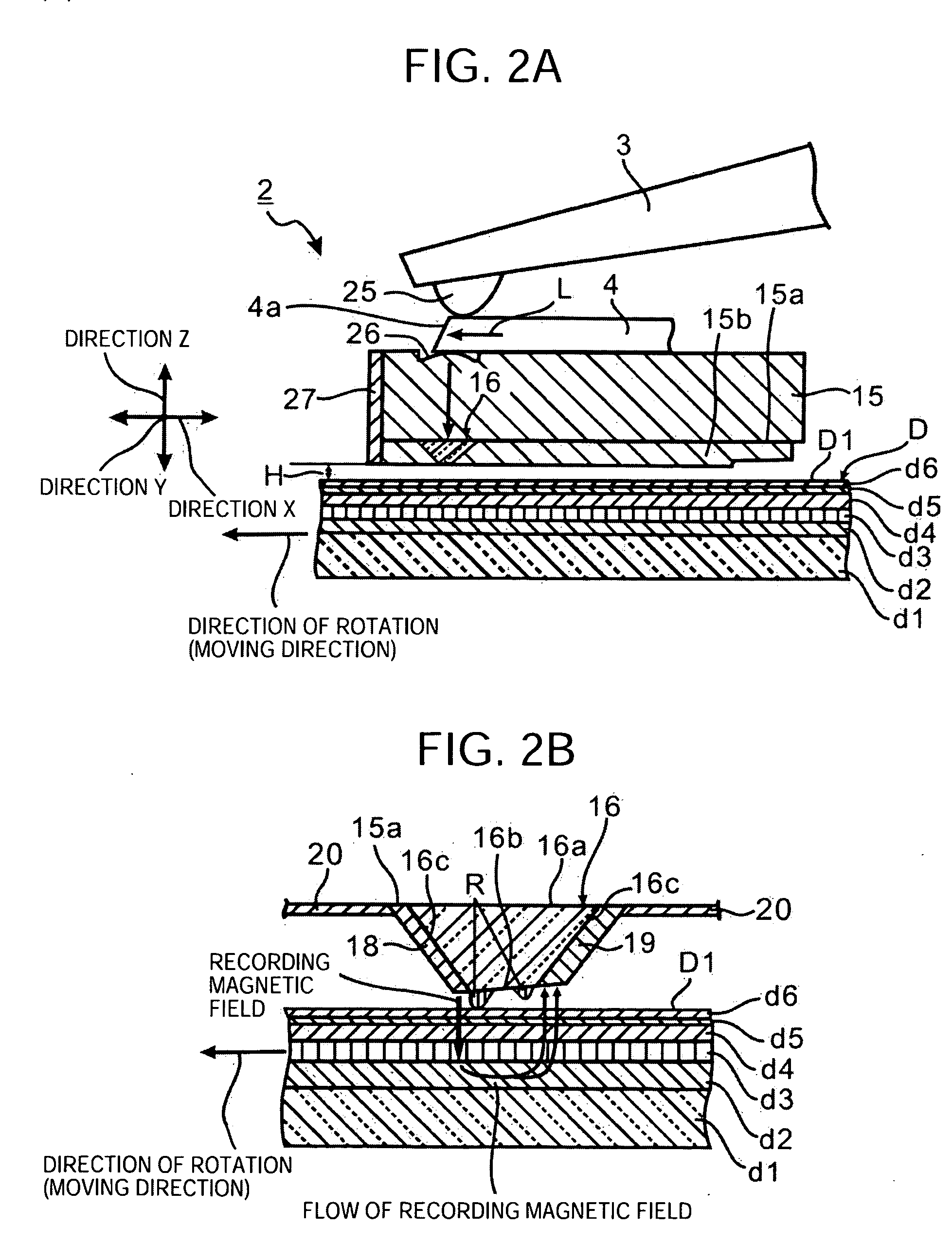
[0038]Now, described will be a near field optical recording element, a near field optical head and an information recording and reproducing device in accordance with a first embodiment of the invention, made reference to FIGS. 1 to 7. The information recording and reproducing device 1 in accordance with the embodiment is a device for writing to a disc (a magnetic recording medium) D including a magnetic recording layer d4 by a perpendicular recording system. In the embodiment, exemplified is an air floating type in which an air flow caused by rotation of the disc D is used to float a near field optical head 2.

[0039]FIG. 1 roughly shows an information recording and reproducing device 1 in accordance with the embodiment. The information recording and reproducing device 1 in accordance with the embodiment comprises a light near field optical head 2, a beam 3 capable of moving in a direction XY parallel to a surface of a disc D (a surface of a magnetic recording medium) for holding on a...

second embodiment

[0085]Now, described will be the near field optical head in accordance with a second embodiment of the invention, made reference to FIGS. 8 and 9. In the second embodiment, components same as those in the first embodiment are marked with the same signs and references to be omitted from description.

[0086]FIG. 8 illustrates an example of a structure of the core 16, the structure being similar to that in FIG. 4, in which metal films (M1, M2, M3 and M4) are further formed on the inclined surfaces (16c1, 16c2, 16c3 and 16c4) of the core 16 and the main magnetic pole 18 and the auxiliary magnetic pole 19 are formed on the metal films M1 and M2.

[0087]The metal film has a function as a light shielding film for preventing the introduced light flux L from being leaked to the outside of the core 16 and is formed so as to achieve a surface plasmon effect of metal. This allows the light flux L to be converged more, so that the near field light N1 can be generated efficiently. Further, the plasmo...

third embodiment

[0092]Now, described will be the near field optical head in accordance with a third embodiment of the invention, made reference with FIGS. 10 and 11. In the third embodiment, components same as those in the first and second embodiments are marked with the same signs and references to be omitted from description.

[0093]FIG. 10 illustrates an example of a structure of a core 36 wherein a bottom surface 36a and an end surface 36b are trapezoid and side surfaces 36c1, 36c2, 36c3 and 36c4 are provided. The end surface 36b is inclined at a predetermined angle with the bottom surface 36a.

[0094]Introduction of the light flux L having the direction of polarization P vertical to an outline 36b1 of the end surface 36b into the core 36 causes the near field lights N1 and N2 to be generated in the vicinity of an outline 36b1 and an outline 36b2. At that time, only the near field light N1 in the vicinity of the outline 36b1 of the core 36, which is closest to the disc surface D1, operates on the ...


PUM


Abstract

A near field optical head includes: a slider provided so as to float from a surface of the magnetic recording medium by a predetermined distance, the slider having a facing surface faced to a surface of the magnetic recording medium; a tipped-shaped near field light generating element formed on the facing surface to have a bottom surface in contact with the facing surface, a top surface formed into a flat surface by cutting a top end of a cone or a pyramid, the flat surface being at a predetermined angle with the bottom surface, and a side surface connecting the bottom surface with the top surface for generating near field light from the top surface; a magnetic pole part formed from a main magnetic pole formed on the side surface and an auxiliary magnetic pole facing the main magnetic pole; a thin film-shaped magnetic circuit connected to the magnetic pole part; and a coil wound around the magnetic circuit.

Description

TECHNICAL FIELD[0001]The present invention relates to a near field optical head capable of using interaction of near field light to record various kinds of information in a recording medium with ultrahigh density and an information recording and reproducing device including the near field optical head.BACKGROUND ART[0002]Light record applying near field light has recently attracted attention as a method for achieving an increase in density of an optical recording apparatus. In accordance with the above, studied has been mounting of a near field light generation element to an optical head in an optical recording apparatus.[0003]Development of optical recording apparatuses with high density has aggressively progressed in accordance with a recent explosive increase in quantity of information such as an image and a moving picture. It has been known that an optical disc represented by a CD (a compact disc) and a DVD (a digital versatile disc) has a limited recording density due to a limi...

Claims


Application Information

Patent Timeline
IPC IPC(8): G11B7/135
CPCG11B5/314G11B2005/0021G11B2005/001
Inventor PARK, MAJUNGOUMI, MANABUHIRATA, MASAKAZU
Owner SEIKO INSTR INC
Learn More