In-band media performance monitoring

a technology of in-band media and video, applied in the field of video delivery, can solve the problems of loss, delay, corruption, etc., and the amount of video impairment caused by loss, delay, disorder, etc., to be uniform, and achieve the effect of improving the quality of video from the point of view of users

Inactive Publication Date: 2008-03-20
ROVI TECH CORP
View PDF13 Cites 113 Cited by
  • Summary
  • Abstract
  • Description
  • Claims
  • Application Information

AI Technical Summary

Problems solved by technology

Because the RTP packets are not transmitted synchronously, but rather are routed individually through the network, certain packets may be lost, delayed, delivered out of sequence, become corrupted, or suffer other mishaps.
While these kinds of mishaps can occur in other applications, such as e-mail communication, they are particularly noticeable in the delivery of video and audio streams.
There are further technical challenges to the delivery of such streamed information in view of the large amount of information that is contained in the video stream and that must be assembled very quickly and reliably into a video presentation by the IP video receiver.
Accordingly, even very limited amounts of defective or late routing of relatively few RTP packets may cause a noticeable and annoying degradation of video quality from the point of view of the user.
However, these tools capture information in terms of RTP packet delivery, rather than in terms of the actual video quality as presented by the IP video receiver.
While sometimes useful as a rough approximation of video delivery quality, these tools do not take into account the fact that IP video receiving equipment usually buffers a significant number of RTP packets in memory, providing a window of opportunity for late or out of order RTP packets to arrive before the video content they contain must be decoded and presented as video.
Finally, the amount of video impairment caused by the loss, delay, disordering, corruption, etc of RTP packets is not uniform, but may depend on the content of the packet.
For example, a packet containing important video control information or parts of important “I” MPEG frames, if despite efforts at error recovery, is not available in time for its video decoding, will cause a comparatively more severe disruption in video quality than the loss of a packet containing only a small part of a less significant “P” MPEG frame.
It is these kinds of subtleties of delivery quality in terms of the video presented by the IP video receiver that tools, which track only the video path performance at the level of RTP packet delivery, are unable to detect.
Moreover, some of these tools are designed to be installed at the video head-end or video server and thus may not scale up to the large number of subscribers envisioned for triple-play networks.
However, this technique usually cannot be implemented successfully because VDSL usually has limited upstream bandwidth, this limited bandwidth not being sufficient to transmit back the actual video stream as presented to the user.
It may be the case that one or more data packets, such as RTP packets may be lost or otherwise unavailable at the time that it is necessary that the decoder-ready packets they encapsulate are needed, resulting in the absence of one or more complete decoder-ready packet available to the media decoder module 108.
For example, if the estimated decoding time stamp of a missing RTP packet is so close to the current system clock time that it is too late for a request for its retransmission to be transmitted, processed, and another copy of the missing RTP packet to be retransmitted, it would be inappropriate to transmit a request to retransmit that RTP packet.

Method used


Image

  • In-band media performance monitoring
  • In-band media performance monitoring
  • In-band media performance monitoring

Examples


Embodiment Construction

[0021]In the following description, for purposes of explanation, numerous specific details are set forth in order to provide a thorough understanding of an embodiment of the present invention. It will be evident, however, to one skilled in the art that the present invention may be practiced without these specific details.

System Overview

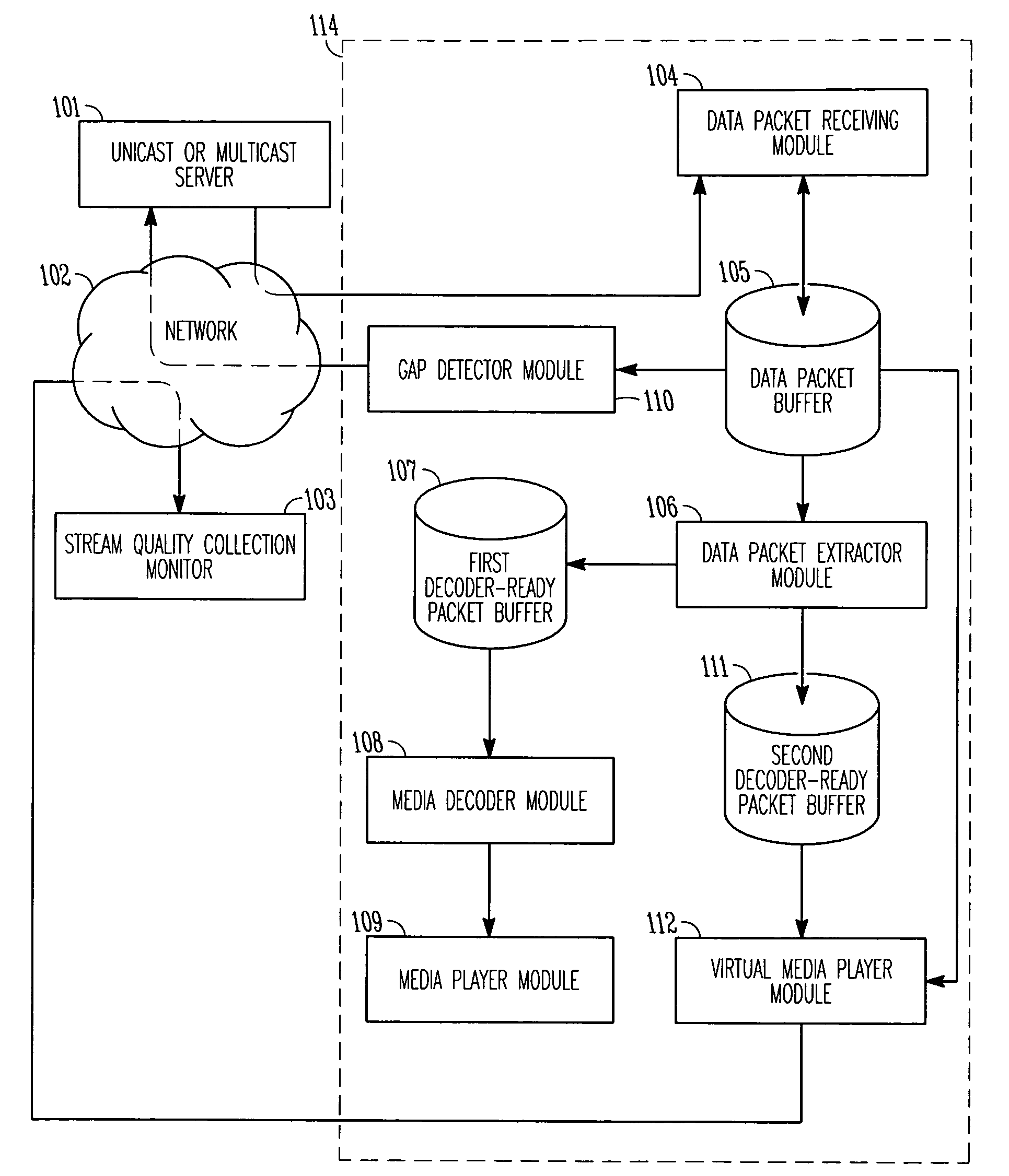
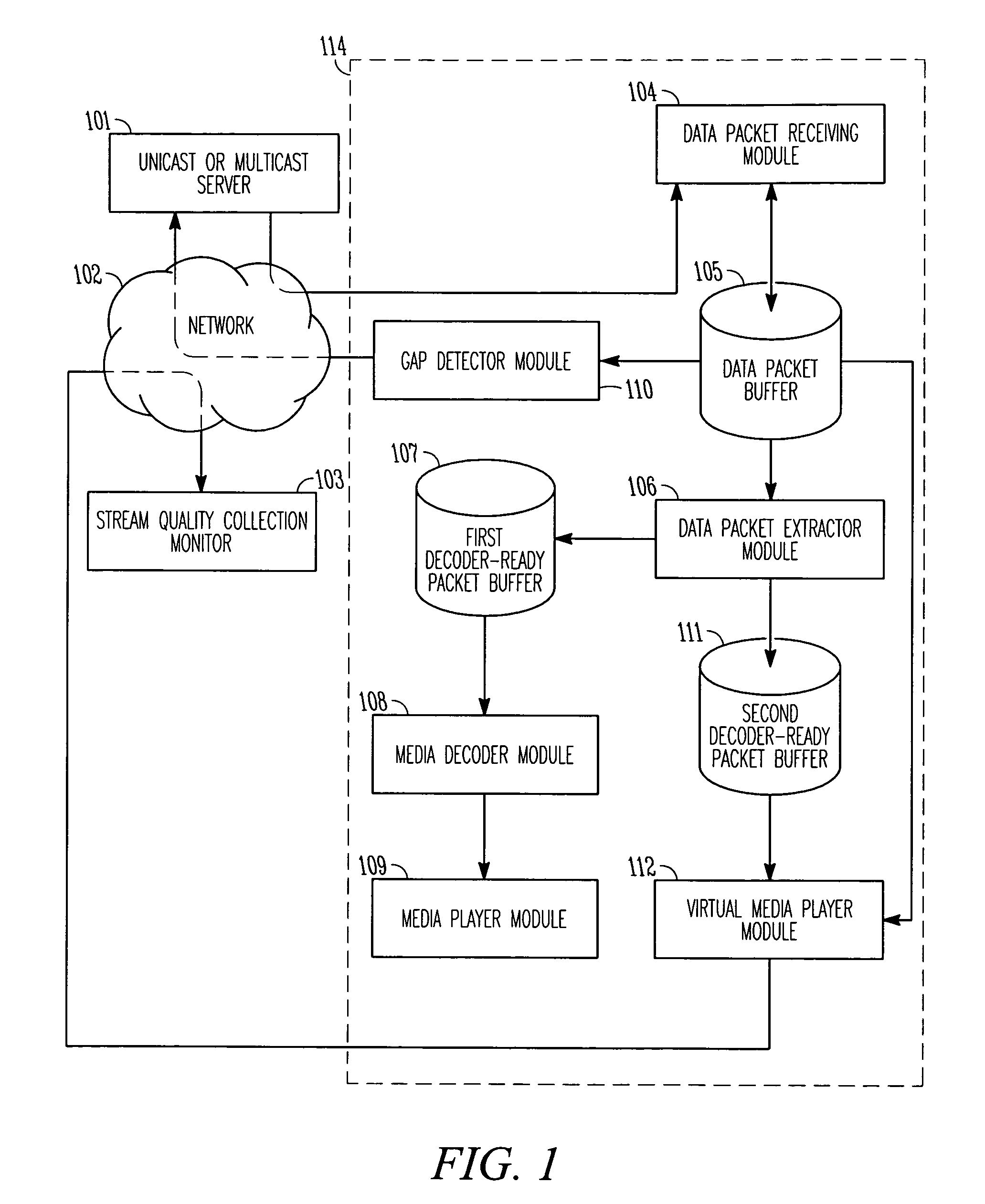
[0022]FIG. 1 illustrates a system for receiving and presenting IP media content, such as, for example, IP video content via set-top box (STB), according to an example embodiment. In this system, a number of modules are shown as well as data buffers and other components. In some embodiments, the modules and other components contained within the dashed rectangle 114 may be contained within a set-top box (STB) or other IP media receiver. In other embodiments, one or more of the modules and components shown within the rectangle 114 may be separate physical components operatively connected to an IP media receiver. It will be appreciated that numerous other...


PUM


Abstract

A method including receiving data packets encapsulating at least part of a media stream, extracting a decoder-ready packet from the data packets, processing the decoder-ready packet; and substantially synchronously with the processing of the decoder-ready packet, generating delivery performance information for the at least part of the media stream, data from which is included in the decoder-ready packet.

Description

TECHNICAL FIELD[0001]The present disclosure relates to the delivery of video via a packet-based network (e.g., the Internet), and specifically to the monitoring of performance quality for video and other media delivered over a network (e.g., a VDSL network).BACKGROUND[0002]Telecommunications providers and others are in the process of deploying wide-scale ‘triple-play’ networks to provide subscribers with Internet communications, streaming video, and streaming audio—including voice communications—in a single subscription service. Many of these triple-play networks use the Internet Protocol (IP) to deliver video services, and since in some cases communications bandwidth to individual subscriber's homes is implemented using very high bit-rate DSL (VDSL), it is useful to monitor subscriber's IP video service quality to, among other things, quickly detect network problems and perform trouble-shooting of the network and video delivery mechanisms.[0003]Video may be delivered over these net...

Claims


Application Information

Patent Timeline
Patent Type & Authority Applications(United States)
IPC IPC(8): H04J3/14
CPCH04L29/06027H04L65/4084H04L65/80H04L65/608H04L65/604H04L65/764H04L65/612H04L65/65H04L65/1101
Inventor SAVOOR, RAGHVENDRA G.LI, ZHIGEMELOS, STEVENKRISHNAMURTHI, GANESHSPOSATO, STEVE
Owner ROVI TECH CORP
Why Eureka
Try Eureka