Motor and fan device using the same

Active Publication Date: 2008-03-20
HITACHI IND EQUIP SYST CO LTD
View PDF4 Cites 16 Cited by
  • Summary
  • Abstract
  • Description
  • Claims
  • Application Information

AI Technical Summary

Benefits of technology

[0013]In a motor which includes a stator including a plurality of one-phase stators configured by a pair of stator cores having claw-type teeth and a coil for generating magnetic flux at the claw-type teeth, and a rotor for generating torque at a rotary shaft, the stator core includes a plurality of split cores having the same shape, and the split cores have a structure in which the split core is provided with a recessed portion and a projected portion to be fitted to the recessed portion. Thereby, by using the plurality of split cores having the same shape, one stator core is formed. By using the two stator cores as a pair, and assembling those so as to be opposed to each other while putting a coil therebetween, a one-phase stator is made. On this occasion, the shape of the split core is molded so that the recessed portions and the projected portions of one stator core are disposed in the positions where those are fitted to the projected portions and the recessed portions of the opposed stator core, respectively. Thereby, the stator can be easily assembled with high accurately. Particularly if the respective projected portions and the recessed portions have such shapes that those are fitted to each other when one split core of the stator core are laid on the other split core of the stator core in an alternate brick laying state, the strength of the stator can be improved.
[0014]Further, in a motor which includes a rotor rotating around a rotary shaft, and a stator formed by causing a plurality of stator cores to oppose to each other which stator cores have columnar core portions in which a plurality of coils disposed on the same plane around the rotary shaft are inserted and claw-type teeth, the stator core has a structure in which the stator core includes a recessed portion at least in one of the columnar core portions, and is provided with a projected portion at least in one of the columnar cores which projected portion is fitted in the recessed portion. In the columnar core portions of the opposing stator cores, the recessed portion is fitted to the projected portion, and the projected portion is fitted in the recessed portion, so that fixing strength and assembling accuracy are improved.
[0015]According to the above described constitution, it is possible to improve facility of assembly and assembling accuracy of the stator by molding the shape of the split cores.
[0016]Further, if the motor having the above described constitution is used in a fan device for example, it is possible to provide a fan device which is reduced in thickness for example, as compared with a conventional fan device.
[0017]According to the present invention, it is possible to provide a motor enhanced in reliability as compared with a conventional motor, and a fan device using it.

Problems solved by technology

Particularly, there is a limit in integrally molding a large output motor in view of the performance of the pressing machine.
Since assembling accuracy of this stator influences the motor characteristics, it is a problem to enhance the assembling accuracy of the stator core.
Further, also in the case of forming the stator cores for one phase by opposing the two stator cores to each other, it becomes a problem to enhance the assembling accuracy.

Method used


Image

  • Motor and fan device using the same
  • Motor and fan device using the same
  • Motor and fan device using the same

Examples


Embodiment Construction

[0037]Hereinafter, embodiments of the present invention will be described by using the drawings.

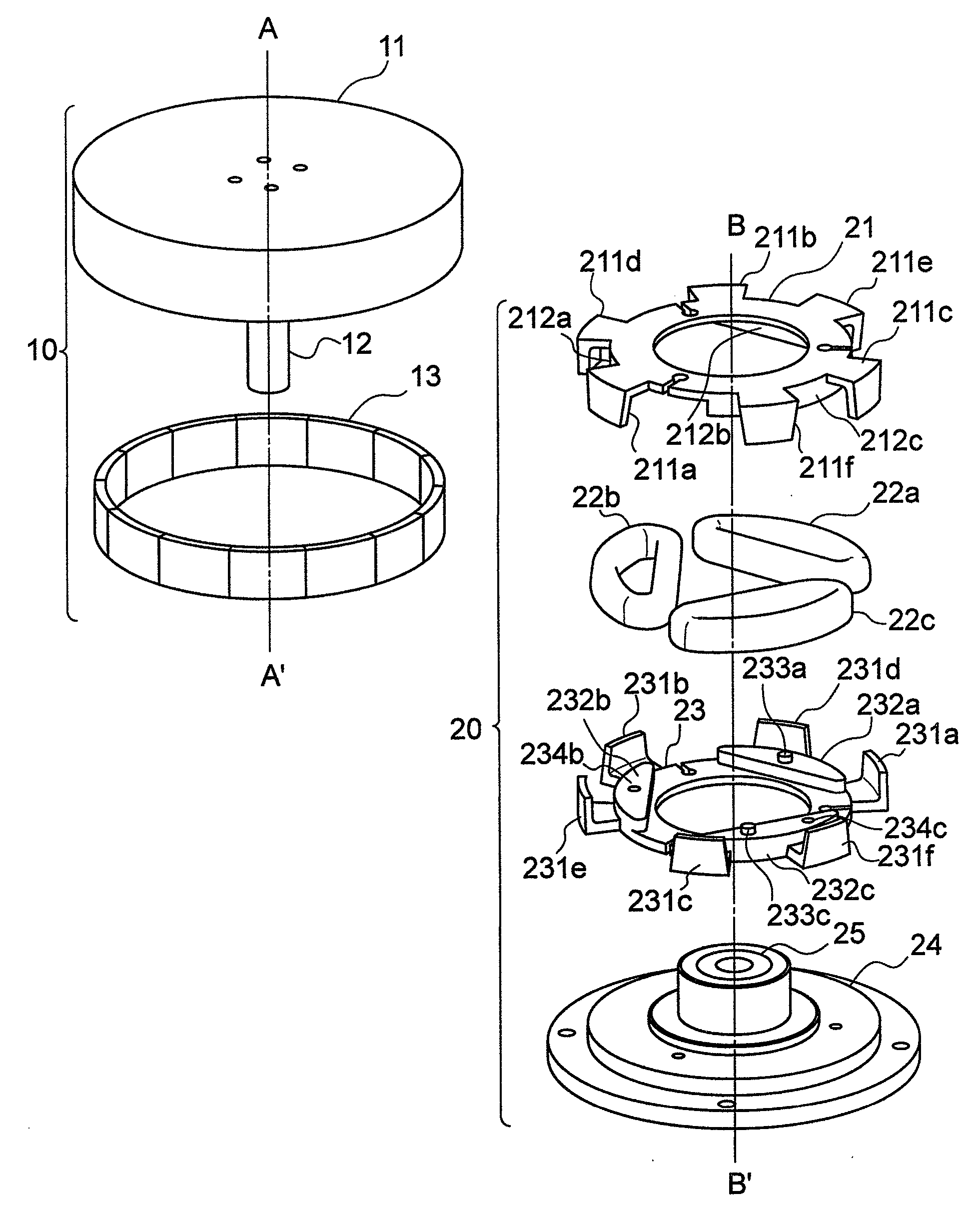
[0038]FIG. 1 shows an embodiment of an outer rotor type three-phase motor which is characteristic of the present invention, and is an exploded view in which a rotor 10 and a stator 20 constituting the motor are divided. The rotor 10 is composed of a rotary member 11 which transmits output power to a load, a cylindrical magnet 13 which is stuck to an inside of the rotary member 11 to generate magnetic flux, and a rotary shaft 12 which is the center of rotation. The rotor 10 is formed by incorporating the magnet 13 in the rotary member 11 integrated with the rotary shaft 12 with a center axis which is the straight line A-A′ shown in FIG. 1.

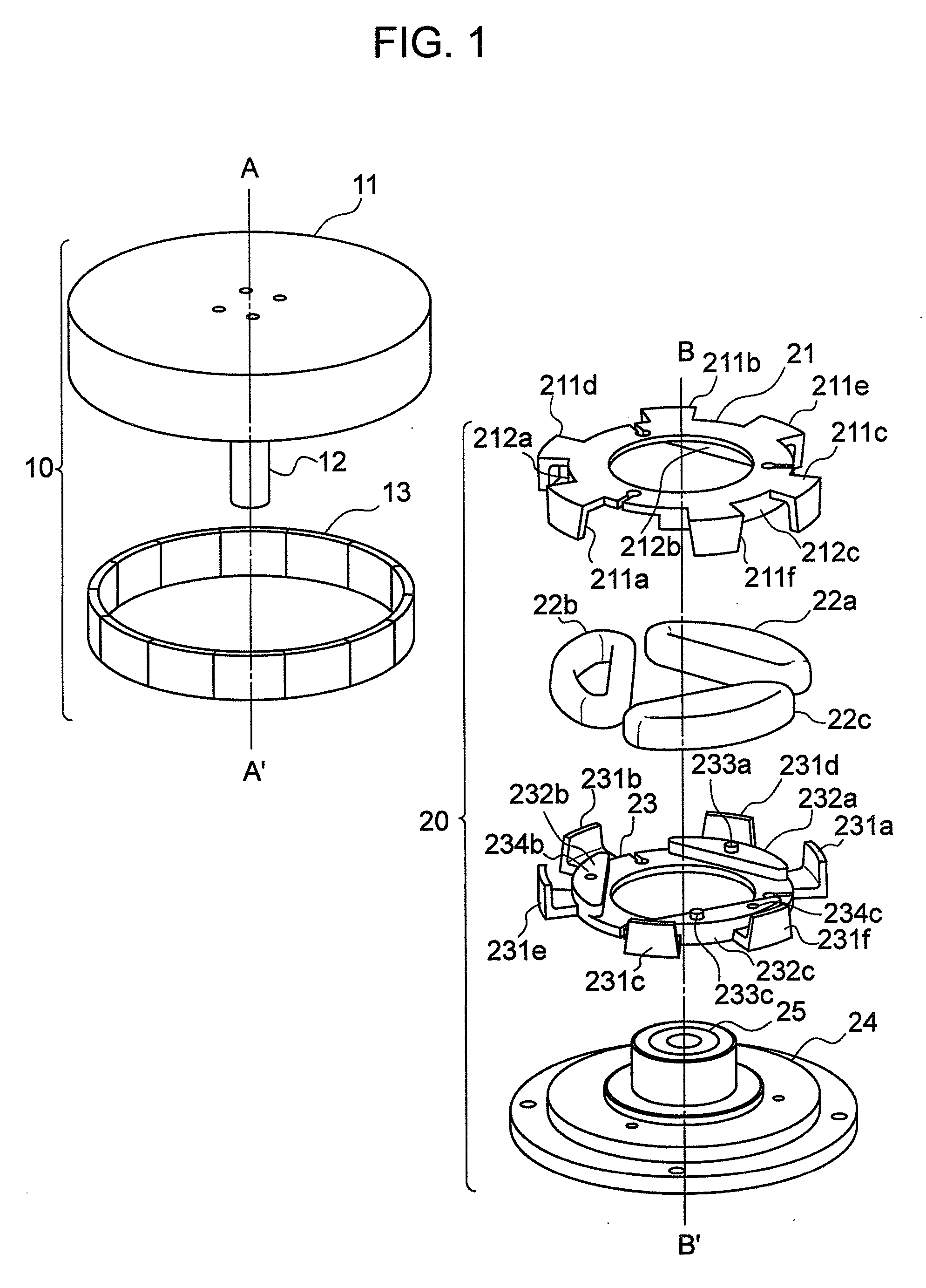
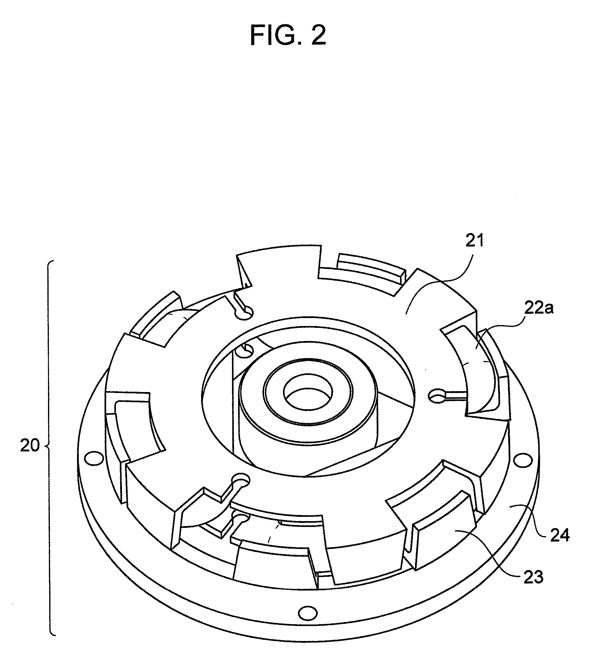
[0039]The stator 20 is generally composed of a coil 22 which allows current to pass in the motor, stator cores 21 and 23 which form a magnetic path of magnetic flux generated by the current of the coil 22, a fixing member 24 for mounting the stator on a p...


PUM


Abstract

The present invention provides a motor which includes a stator including a plurality of one-phase stators composed of a pair of stator cores having claw-type teeth and a coil for generating magnetic flux at the claw-type teeth, and a rotor for generating torque at a rotary shaft, wherein the stator core includes a plurality of split cores having the same shape, and the split cores are formed to have a recessed portion and a projected portion to be fitted in the recessed portion. Thereby, by using a plurality of the split cores having the same shape, one stator core is formed. On this occasion, the shape of the split cores is molded so that the recessed portion and the projected portion of one stator core are disposed at positions at which those are fitted to the projected portion and the recessed portion of the opposing stator core, respectively.

Description

CROSS REFERENCES TO RELATED APPLICATION[0001]The present application claims priority from Japanese application JP 2006-253720 filed on Sep. 20, 2006, the content of which is hereby incorporated by reference into this application.BACKGROUND OF THE INVENTION[0002]1. Field of the Invention[0003]The present invention relates to an art of providing a motor.[0004]2. Description of Related Art[0005]Motors are widely used in various fields. As one form of the motors, there is a motor having a claw-type magnetic pole. For example, JP-A-2001-161054 and JP-A-2003-513599 disclose the structure thereof.[0006]First, in JP-A-2001-161054, a stator for one phase of the motor is composed of a circular coil through which current passes, a pair of claw-type magnetic poles, and a magnetic body surrounding the coil to form a magnetic path together with the claw-type magnetic poles.[0007]In the case of a three-phase motor, its stator can be formed by using three sets of the above described stators. When t...

Claims


Application Information

Patent Timeline
IPC IPC(8): H02K1/12F04D29/70
CPCF04D25/06F04D25/08F04D29/701F04D25/0646H02K1/145H02K37/14F04D29/703H02K21/22H02K2201/12
Inventor MASAKI, RYOSOENOMOTO, YUJIITO, MOTOYAAMANO, HISATOMORINAGA, SHIGEKIYAMAZAKI, KATSUYUKIEBINE, KAZUHIDE
Owner HITACHI IND EQUIP SYST CO LTD
Why Eureka
Try Eureka