Method and apparatus of monitoring a machine

Active Publication Date: 2008-03-20
BAKER HUGHES INC
View PDF17 Cites 50 Cited by
  • Summary
  • Abstract
  • Description
  • Claims
  • Application Information

AI Technical Summary

Problems solved by technology

However, at least some known vibration monitoring systems are not configured to record, transmit, and / or process component speed and vibration data simultaneously and as such, may need to utilize component speed and vibration data recorded at differing times.

Method used


Image

  • Method and apparatus of monitoring a machine
  • Method and apparatus of monitoring a machine
  • Method and apparatus of monitoring a machine

Examples


Embodiment Construction

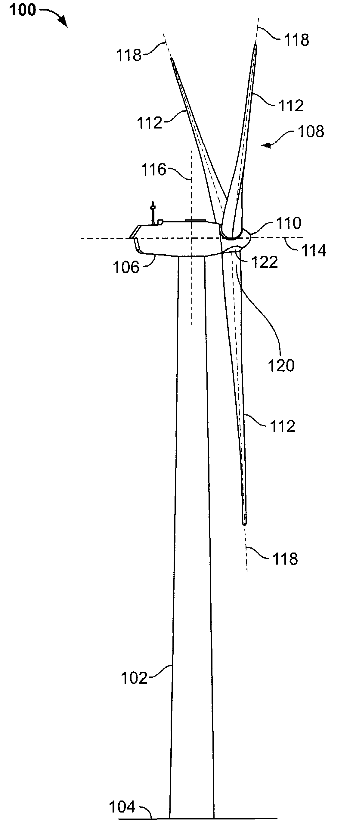
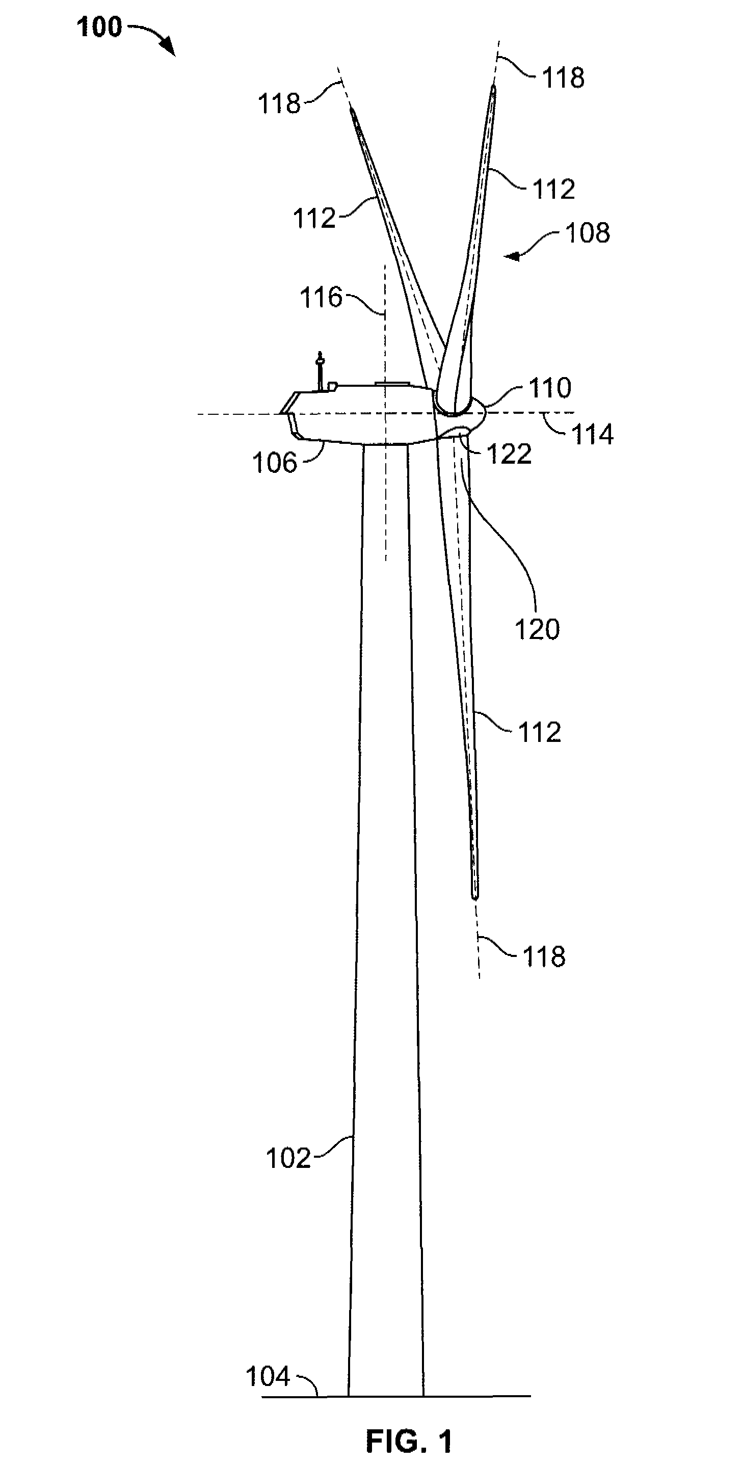
[0013]FIG. 1 is a schematic illustration of an exemplary wind turbine generator 100. In the exemplary embodiment, wind turbine generator 100 is a horizontal axis wind turbine. In the exemplary embodiment, wind turbine generator 100 is a 1.5 megawatt (MW) series wind turbine generator 100 commercially available from General Electric, Schenectady, N.Y. Alternatively, wind turbine 100 may be a vertical axis wind turbine. Wind turbine 100 has a tower 102 extending from a supporting surface 104, a nacelle 106 mounted on tower 102, and a rotor 108 coupled to nacelle 106. Rotor 108 has a rotatable hub 110 and a plurality of rotor blades 112 coupled to hub 110.

[0014]In the exemplary embodiment, rotor 108 has three rotor blades 112. In an alternative embodiment, rotor 108 may have more or less than three rotor blades 112. In the exemplary embodiment, tower 102 is fabricated from tubular steel and has a cavity (not shown in FIG. 1) extending between supporting surface 104 and nacelle 106. In ...


PUM


Abstract

A monitoring system for a machine is provided. The machine includes at least one movable member including at least one sensor configured to generate at least one speed measurement of the moveable member. The machine also includes at least one processor coupled in electronic data communication to the sensor. The sensor is configured to generate at least one time stamp value for the at least one speed measurement signal. The at least one processor is configured to generate a plurality of time-stamped speed measurement signals of the at least one moveable member. The processor is further configured to determine a prioritization of the plurality of time-stamped speed measurement signals as a function of at least one predetermined temporal value.

Description

BACKGROUND OF THE INTENTION[0001]This invention relates generally to machines and more particularly, to methods and apparatus for monitoring wind turbines.[0002]Generally, a wind turbine generator includes a turbine that has a rotatable hub assembly including multiple blades. The hub assembly is coupled to a rotor and the blades transform mechanical wind energy into a mechanical rotational torque that drives one or more generators via the rotor. The generators are generally, but not always, rotationally coupled to the rotor through a gearbox. The gearbox steps up the inherently low rotational speed of the rotor to enable the generator to efficiently convert the rotational mechanical energy into electrical energy that is supplied to a utility grid. Gearless direct drive wind turbine generators also exist. Generally, the rotor, generator, gearbox and other components are mounted within a housing or nacelle, that is positioned atop a base, such as truss, lattice or tubular tower.[0003]...

Claims


Application Information

Patent Timeline
Patent Type & Authority Applications(United States)
IPC IPC(8): F03D9/00G01M99/00
CPCF03D7/047F03D11/0091F05B2270/327Y02E10/722G01P1/122G01P1/127Y02E10/723F05B2270/807F03D17/00Y02E10/72
Inventor MALAKHOVA, OLGAGRANT, JOHN WESLEYSCHMID, JAMES JOSEPHCLARK, TIMOTHY J.
Owner BAKER HUGHES INC
Why Eureka
Try Eureka