Assembled Battery and Manufacturing Method Thereof

a technology of assembled batteries and manufacturing methods, applied in the direction of batteries, sustainable manufacturing/processing, flat cell grouping, etc., can solve the problems of unfavorable use, difficult automation of operation, and inability to meet the requirements of continuous operation, and achieve excellent endurance-reliability and maintainability.

Active Publication Date: 2008-03-20
ENVISION AESC JAPAN LTD
View PDF10 Cites 55 Cited by
  • Summary
  • Abstract
  • Description
  • Claims
  • Application Information

AI Technical Summary

Benefits of technology

[0008] It is an object of the present invention to provide a combined battery for which ultrasonic welding of electrode tabs themselves of flat-type cells is easily performed, being excellent in endurance-reliability and maintainability, and a method for producing the same.

Problems solved by technology

But, these welding methods have the following problems.
First, in the case of welding by using an ultrasonic welding machine, because only the electrode tabs to be welded (the plus and the minus tabs to compose a set), have to be sandwiched by the head of the ultrasonic welding machine, welding can not be performed in the laminated state of all the combined batteries, and to ensure an insertion space for the head, it is necessary for other flat type cells except those to be welded to be moved (to be opened vertically in the lamination direction) once, therefore, not only the operation is troublesome, but the operation has such problems that automation of the operation is difficult and unnecessary stress is applied to the electrode tabs already welded, and the like.
Next, in the case of mechanical bonding, because mechanical means including bolts, nuts and washers, has to be used, it could generate contact resistance variation or loosening due to vibration, and thus there are problems in endurance-reliability and maintainability.

Method used


Image

  • Assembled Battery and Manufacturing Method Thereof
  • Assembled Battery and Manufacturing Method Thereof
  • Assembled Battery and Manufacturing Method Thereof

Examples


embodiment 1

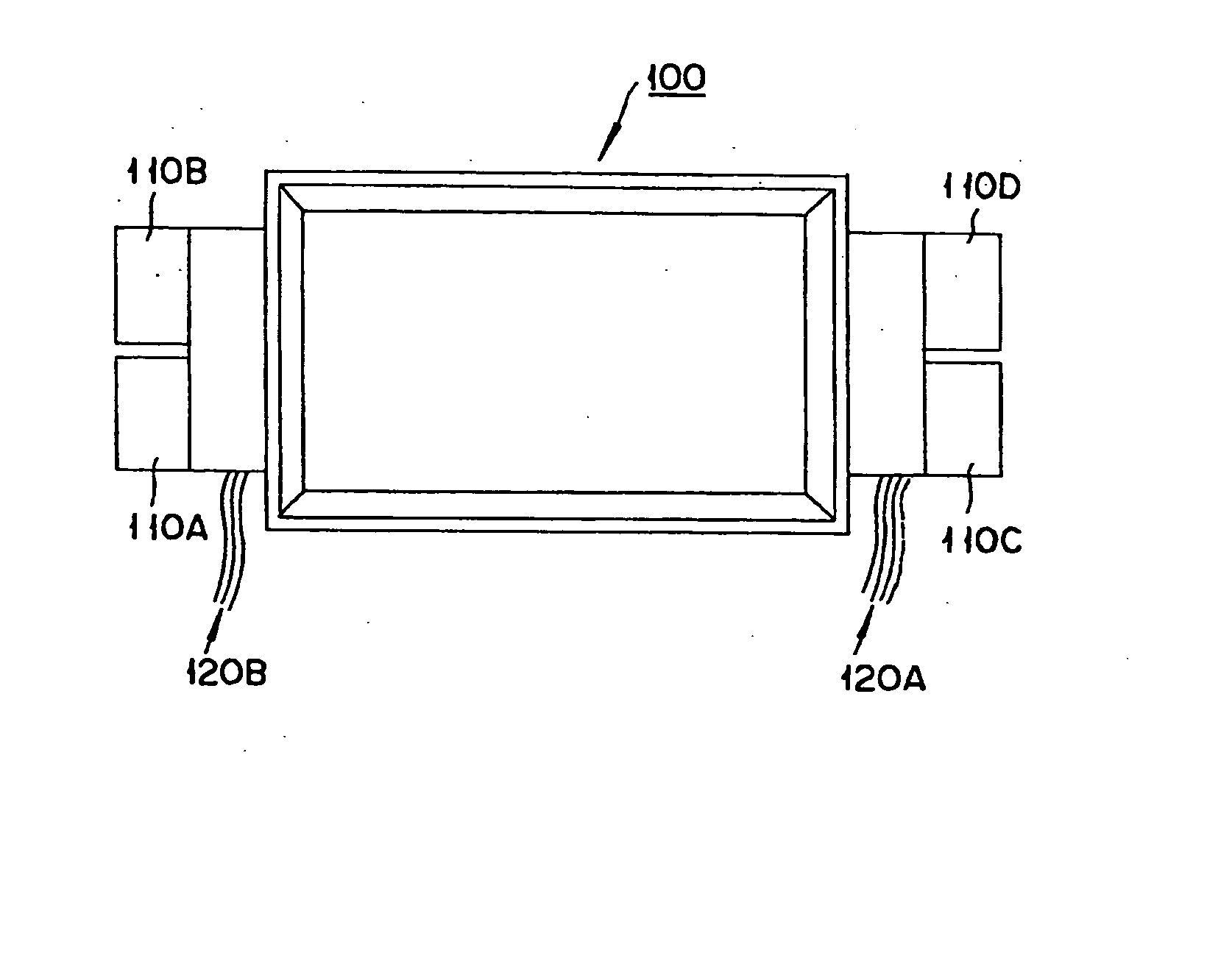
[0065]FIG. 1 is an outline view of a combined battery according to Embodiment 1 relevant to the present invention. The combined battery 100 according to the present Embodiment includes 8 sheets of flat-type cells by laminating thereof in the thickness direction thereof so that polarity of electrode tabs is alternately set. The combined battery 100 according to the present Embodiment includes welding parts of the electrode tabs to connect the flat-type cells themselves in series, to compose a set when all the flat-type cells are laminated, separating at a plurality of positions of the combined battery, and such a structure that all the flat-type cells are electrically connected in series by welding each of the welding parts. Specifically, the flat-type cell is rectangular in shape when viewed from the top and the welding parts of electrode tabs are arranged so that the positions thereof may be changed in the length direction (the horizontal direction in the figure) thereof or in the ...

embodiment 2

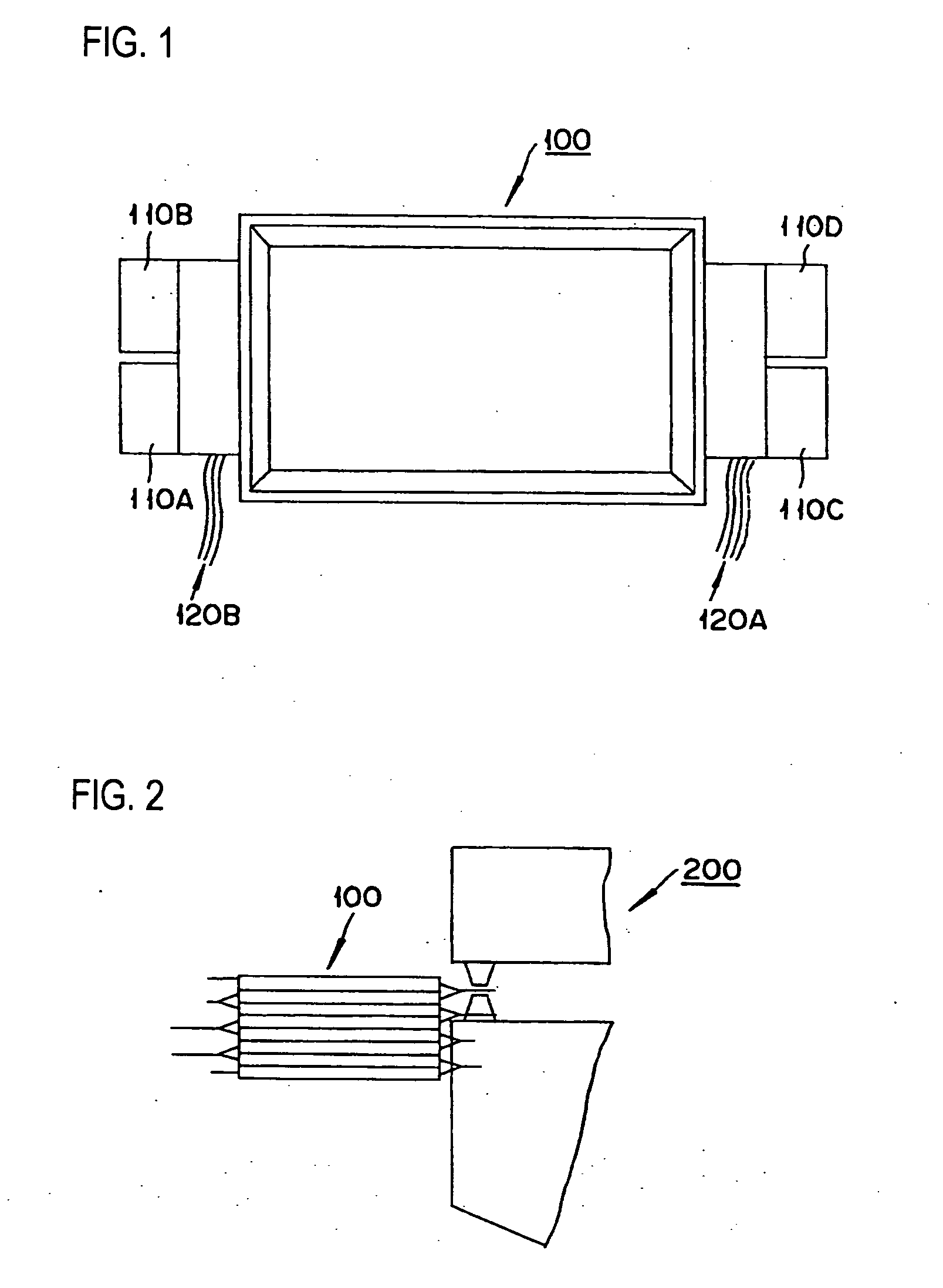
[0093]FIG. 8 is an outline view of a combined battery according to Embodiment 2 relevant to the present invention. A combined battery 300 according to the present Embodiment is one formed by laminating 12 sheets of flat-type cells in the thickness direction of thereof. Each one of electrode tabs pulled out from both sides of the flat-type cell has a specific shape in each lamination layer position thereof so that welding positions are different each other, when 12 sheets of the flat-type cells are laminated in order. The electrode tabs of the flat-type cells are electrically connected in series by welding with the ultrasonic welding machine 200 shown in FIG. 2. The electrode tabs of the combined battery 300 are arranged so that the protruding parts 310A, 310B, 310C and 310D thereof are separated into 4 directions as shown in FIG. 8 in completely assembled state. In the flat-type cell 300, all of the 12 sheets of flat-type cells are electrically connected in series in completely asse...

embodiment 3

[0109] A combined battery according to the present Embodiment is one formed by laminating 8 sheets of flat-type cells in the thickness direction thereof in the prescribed combination of the flat-type cells having 3 types of electrode tab shapes as shown in FIG. 17. Each one of electrode tabs pulled out from both sides of the flat-type cell has a specific shape in each lamination layer position thereof so that welding positions may be in different positions when 8 sheets of the flat-type cells are laminated in order. The electrode tabs of the flat-type cells are electrically connected in series by welding with the ultrasonic welding machine 200 shown in FIG. 2. The electrode tabs of the combined battery are arranged so that the protruding parts thereof are separated into 4 directions in the same way as FIG. 8 shown in Embodiment 2 in completely assembled state. In the combined battery, all of the 8 sheets of flat-type cells are electrically connected in series, in completely assemble...


PUM

PropertyMeasurementUnit
voltageaaaaaaaaaa
voltageaaaaaaaaaa
angleaaaaaaaaaa

Abstract

A combined battery (100) comprising a plurality of flat-type cells (10A to 10F) by laminating thereof so that polarity of electrode tabs (11A to 11F and 12A to 12F) is alternately set, wherein welding parts to connect in series the flat cells themselves, to compose a set when all the flat-type cells (10A to 10F) are laminated, are separated at a plurality of positions of the combined battery, and the flat-type cells having such a structure that all the flat-type cells are electrically connected in series by welding each of the welding parts.

Description

TECHNICAL FIELD [0001] This invention relates to a combined battery for which ultrasonic welding of electrode tabs themselves of flat-type cells is easily performed and a method for producing the same. BACKGROUND ART [0002] Recently, responding to rising environmental awareness, there is a movement to shift the power source of automobiles from engines using fossil fuel, to motors utilizing electrical energy. Therefore technology of a battery to be used as the power source of motors has rapidly been developing. [0003] An automobile is desired to mount a compact-size and light-weight battery, capable of charging and discharging high power frequently, and excellent in vibration resistance and heat radiation performance. In response to such requirements, a combined battery constructed by connecting a large number of flat-type cells in series, has recently been developed as shown in JP-A-2004-31136. DISCLOSURE OF INVENTION [0004] A combined battery providing higher voltage is desired so ...

Claims


Application Information

Patent Timeline
Patent Type & Authority Applications(United States)
IPC IPC(8): H01M6/42H01M2/20H01M6/46H01M50/211H01M50/51H01M50/516H01M50/548H01M50/557H01M50/569
CPCH01M2/1061Y10T29/49108H01M2/206H01M6/46H01M10/482H01M2220/20Y02E60/10H01M50/516H01M50/51H01M50/569H01M50/548H01M50/211H01M10/0413H01M10/4207H01M10/613H01M10/625H01M10/647H01M10/6555H01M10/6557H01M10/6566H01M50/24Y02P70/50H01M50/20H01M50/50H01M6/42
Inventor WATANABE, MASASHITANJOU, YUUJIOTA, MASAYASUENOKIDA, TSUYOSHIKISHIMOTO, HIROAKIAMAGAI, RYUICHISEGAWA, TERUOHAYAMI, MUNETO
Owner ENVISION AESC JAPAN LTD
Why Eureka
Try Eureka