
Dynamic patient positioning system

a patient positioning and dynamic technology, applied in the field of radiation therapy, can solve the problems of significant time and effort, and significantly limit the number of patients

Inactive Publication Date: 2008-03-20
VARIAN MEDICAL SYSTEMS
View PDF12 Cites 28 Cited by
  • Summary
  • Abstract
  • Description
  • Claims
  • Application Information

AI Technical Summary

Benefits of technology

[0010] Various embodiments of the invention include systems and methods of moving one or more patients from a preparation area to one or more treatment areas. One or more devices configured to transport patients is optionally further configured to position patients relative t...

Problems solved by technology

Patient positioning is typically performed under manual control and, thus, can require significant time and effort.
This time and effort may significantly limit the number of patients that can be treated by a treatment system.

Method used


Image

  • Dynamic patient positioning system
  • Dynamic patient positioning system
  • Dynamic patient positioning system

Examples


Embodiment Construction

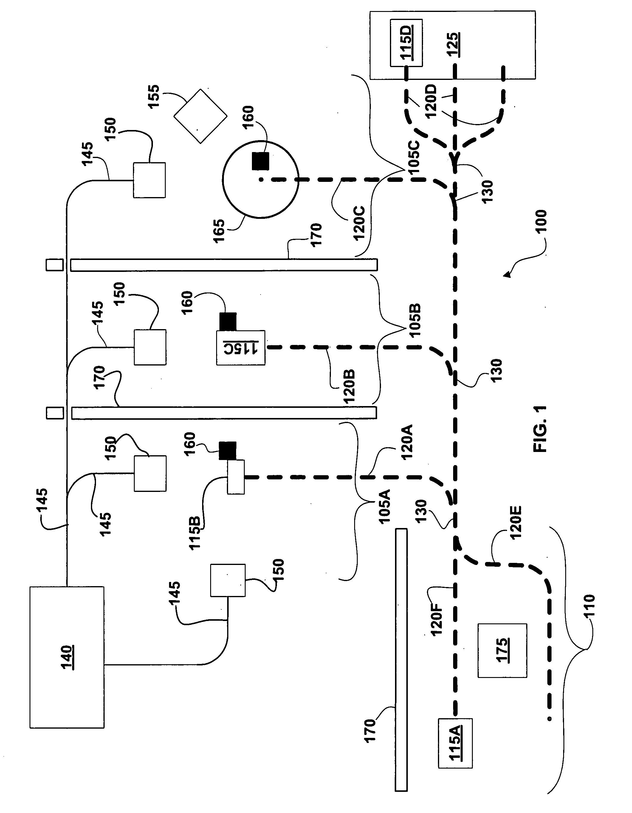
[0024] A patient treatment system includes an automated patient transporter configured to transport a patient from a preparation area to a treatment area. In some embodiments the automated patient transporter is configured to both transport the patient to the treatment area and to finely position the patient relative to a treatment beam after arriving at the treatment area. Typically, the preparation area is separate and / or shielded from the treatment area such that a first patient can be prepared in the preparation area while a second patient receives treatment in the treatment area. In some embodiments, the automated patient transporter is configured to transport a patient to one of a number of alternative treatment areas. For example, an automated patient transporter can be programmed to transport the patient to a specific treatment area responsive to a patient treatment plan or a treatment schedule.

[0025]FIG. 1 illustrates a Treatment System, generally designated 100. In variou...


PUM


Abstract

A patient treatment system includes one or more automated patient transporters configured to move a patient from a preparation area to one of a plurality of alternative treatment areas, and to position the patient relative to a therapeutic radiation beam. Both transportation of the patient and positioning of the patient are optionally performed while the patient is secured to one of the patient transporters. A control system may be used to both position and transport the patient responsive to a patient treatment plan.

Description

CROSS-REFERENCE TO RELATED APPLICATIONS [0001] This application claims benefit of U.S. Provisional Patent Application 60 / 859,675 filed Nov. 17, 2006 and entitled “Dynamic Patient Positioning System”; [0002] this application is also a continuation-in-part of U.S. patent application Ser. No. 11 / 415,974 filed May 1, 2006 and entitled “Patient Support Systems” which in turn claims benefit of U.S. Provisional Patent Application 60 / 676,138 filed Apr. 29, 2005 and entitled “Radiation Systems, Components Thereof, and Methods of Using the Same”; [0003] this application is also a continuation-in-part of U.S. patent application Ser. No. 11 / 447,532 filed Jun. 5, 2006 and entitled “Multiple Beam Path Particle Source”; [0004] this application is related to U.S. patent application Ser. No. 11 / 415,957, filed May 1, 2006 and entitled “Systems and Methods for Treating Patients Using Radiation”; U.S. patent application Ser. No. 11 / 415,866, filed May 1, 2006 and entitled “Radiation Systems”; and U.S. p...

Claims


Application Information

Patent Timeline
IPC IPC(8): A61G5/08G06F7/00G06Q50/00
CPCA61G1/017A61G1/0231A61G5/046A61G2200/325A61G2210/50A61N5/1049A61N5/1079A61N2005/1063G06F19/327G06F19/3481G06Q50/22A61G1/0212A61G1/0275A61G1/0293A61G5/006G16H20/40G16H30/20G16H40/20A61B6/04A61B6/0407A61B6/0478A61B6/0492A61B6/08A61B6/4411A61B6/547A61B6/582A61B2560/0223A61B2560/0228A61N5/1048A61N5/1075A61N2005/1051A61N2005/1059A61N2005/1061A61B34/20A61B90/39A61B2034/2046A61B2090/363A61B2090/364A61B2090/3904A61B2090/392A61B2090/3929A61B2090/3937A61B2090/3966A61B2090/3979A61B2090/3983A61B2090/3995
Inventor GUERTIN, TIMOTHY E.MARC, MARCEL R.
Owner VARIAN MEDICAL SYSTEMS
Learn More