Apparatus at a spinning preparation machine in which a clothed, rapidly rotating roller is located opposite at least one component at a spacing

a technology of garments and preparation machines, which is applied in the direction of carding machines, textiles and papermaking, fibre treatment, etc., can solve the problems of widening out the cylinder and also the clothing, narrowing the carding gap, and reducing the number of garments, so as to avoid or mitigate the effect of time loss

Inactive Publication Date: 2008-03-27
TRUETZSCHLER GMBH & CO KG
View PDF3 Cites 3 Cited by
  • Summary
  • Abstract
  • Description
  • Claims
  • Application Information

AI Technical Summary

Benefits of technology

[0010]It is an aim of the invention, accordingly, to provide an apparatus of the kind described at the beginning that avoids or mitigates the mentioned disadvantages and that especially makes it possible, by means that are simple and that save time, to set a modified carding gap when profiled carrier members having different parameters (e.g. construction, properties) are being replaced.

Problems solved by technology

Manual input of those parameters by the machine operator is onerous and may be associated with errors.
Increasing the speed of rotation of the cylinder, for example in order to increase the cleaning action, results in a widening-out of the cylinder and also of the clothing, on account of the centrifugal force, and therefore in a narrowing of the carding gap.
The greater heating of high-performance flat cards that is caused thereby results in greater thermoelastic deformation which, because of the non-uniform distribution of the temperature field, affects the set spacings of the active surfaces.
In extreme cases, the gap set between the active surfaces can be completely consumed as a result of thermal expansion so that components in relative motion collide.
The consequence, then, is major damage to the high-performance flat card concerned.
All this means that, especially, the generation of heat in the working region of the flat card can result in disparate thermal expansion when the temperature differences between the components are too great.
However, a large carding gap results in undesirable nep formation in the carded sliver.
Moving the elements located opposite one another towards one another results in a change in the spacing (carding gap) over the entire width of the machine.
In relation to the cylinder, a further problem lies in the fact that it is unevenly heated over the working width as a result of varying coverage by material and gap variations caused by manufacturing tolerances.
In addition, the heat is dissipated to a greater extent in the edge regions than in the middle, leading to a build-up of heat there.
This results in a temperature gradient from the middle of the working width to the edges.
The disparate thermal expansion caused thereby gives rise to the cylinder becoming distended outwards in a convex shape (bulging) and accordingly leads to a deterioration of the carding gap.
Consequently, the result of carding is adversely affected.
It is disadvantageous that, as a result thereof, the carding gap is uneven over the width of the flat card and, in the middle region, there is a risk of collision between the components.
This problem also occurs when a complete set (plurality) of card flats, each comprising a profiled carrier member and carding element, in the revolving card top unit of a flat card is replaced by a set having a different constructional arrangement and / or being made of a different material.
In the afore-mentioned cases, determining and inputting the properties of the at least one new profiled carrier member for modification of the carding gap is labour-intensive.

Method used


Image

  • Apparatus at a spinning preparation machine in which a clothed, rapidly rotating roller is located opposite at least one component at a spacing
  • Apparatus at a spinning preparation machine in which a clothed, rapidly rotating roller is located opposite at least one component at a spacing
  • Apparatus at a spinning preparation machine in which a clothed, rapidly rotating roller is located opposite at least one component at a spacing

Examples


Embodiment Construction

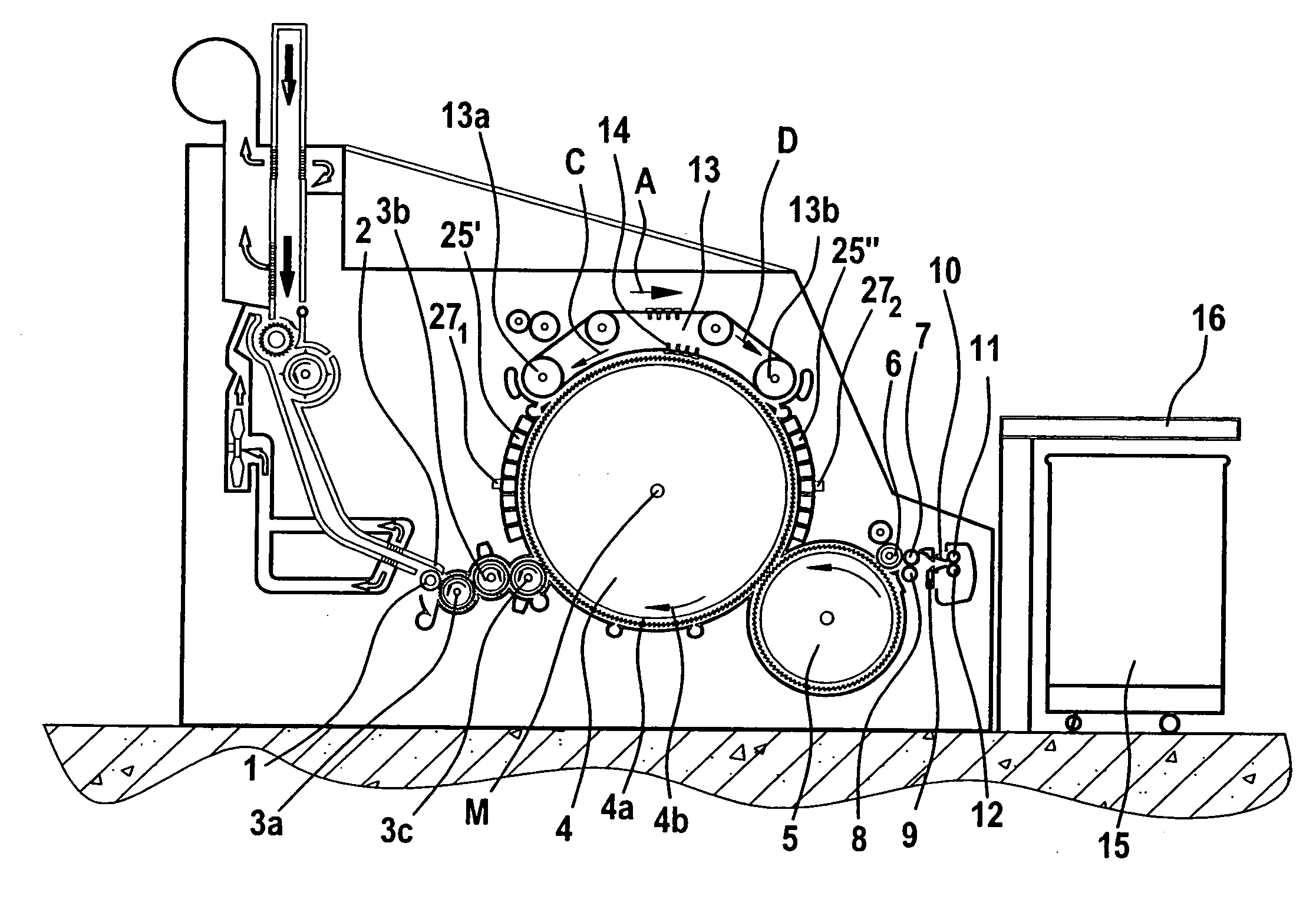
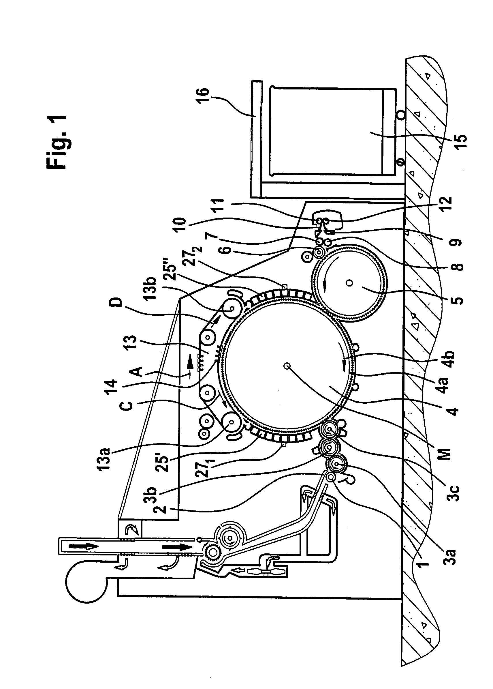
[0020]With reference to FIG. 1, a flat card, for example, a TC 03 flat card made by Trützschler GmbH & Co. K.G. of Mönchengladbach, Germany, has a feed roller 1, feed table 2, lickers-in 3a, 3b, 3c, cylinder 4, doffer 5, stripper roller 6, nip rollers 7, 8, web-guiding element 9, web funnel 10, delivery rollers 11, 12, revolving card top 13 having card top guide rollers 13a, 13b and flats 14, can 15 and can coiler 16. The directions of rotation of the rollers are indicated by curved arrows. Reference letter M denotes the centre (axis) of the cylinder 4 and reference letter A denotes the working direction. Reference 4a denotes the clothing and reference 4b denotes the direction of rotation of the high-speed cylinder 4. Reference letter C denotes the direction in which the revolving card top 13 revolves at the carding location and reference letter D denotes the return transport direction of the flats 14. In the pre-carding region—between the licker-in 3c and the back card top guide ro...


PUM

PropertyMeasurementUnit
speedaaaaaaaaaa
centrifugal forceaaaaaaaaaa
temperatureaaaaaaaaaa

Abstract

In an apparatus at a spinning preparation machine, especially a flat card, roller card or the like, a clothed, rapidly rotating roller is located opposite at least one component at a spacing. In order, by means that are simple and that save time, to make it possible to set a modified carding gap when components having different parameters (construction, properties) are replaced, the component has an electronic storage unit in which information relating to the nature of the component is arranged to be stored. A writing device for writing in the information and a reading device for reading out the information may be provided.

Description

CROSS REFERENCE TO RELATED APPLICATION[0001]This application claims priority from German Patent Application No. 10 2006 045 047.7 dated 21 Sep. 2006, the entire disclosure of which is incorporated herein by reference.BACKGROUND OF THE INVENTION[0002]The invention relates to an apparatus at a spinning preparation machine, especially a flat card, roller card or the like, wherein a clothed, rapidly rotating roller is located opposite at least one component at a spacing, the spacing being influenced by the nature and / or number of components.[0003]In calculating and setting carding gaps it is known to make use of a known arrangement of the machine in question and its components, with material-related and construction-related parameters of components and component groups also being used for calculations. If the configuration of such a machine is then changed in respect of the nature or number of the components in question, it may well be necessary to modify the calculation and setting of ...

Claims


Application Information

Patent Timeline
Patent Type & Authority Applications(United States)
IPC IPC(8): D01G15/28
CPCD01G15/08D01G31/00D01G15/28
Inventor TOBBEN, ROBERT
Owner TRUETZSCHLER GMBH & CO KG
Why Eureka
Try Eureka