Method for control of thermoacoustic instabilities in a combustor

a combustor and thermoacoustic instability technology, applied in the ignition of the turbine/propulsion engine, engine starters, lighting and heating apparatus, etc., can solve the problems of affecting the stability of the combustor, structural damage to the combustor components, and thermoacoustic instabilities, so as to reduce the effect of thermoacoustic instabilities

Active Publication Date: 2008-03-27
RTX CORP
View PDF17 Cites 38 Cited by
  • Summary
  • Abstract
  • Description
  • Claims
  • Application Information

AI Technical Summary

Benefits of technology

[0007]The present invention is a method for controlling a temperature distribution within a combustor having a plurality of chamber sections comprising controlling a fuel-to-air ratio in the chamber sections. At least two chamber sections have different fuel-to-air ratios to create a non-uniform temperature distribution within the combustor to reduce thermoacoustic instabilities.

Problems solved by technology

Thermoacoustic instabilities arise in gas turbine and aero-engines when acoustic modes couple with unsteady heat released due to combustion in a positive feedback loop.
These instabilities can lead to large pressure oscillations inside the combustor cavity, thereby affecting its stable operation and potentially causing structural damage to the combustor components.
However, these solutions suffer from several disadvantages.
In particular, they introduce additional weight and may be expensive to implement.
In addition, resonators are effective only over a limited range of frequencies and become ineffective if frequency of the instability changes because of, for example, changes in operating conditions.
These passive devices have to be cooled, which may detrimentally affect the efficiency of the engine.
However, on account of complex combustion physics, the exact physical mechanism underlying the initiation and sustenance of instabilities such as screech typically is not understood.
Furthermore, there are implementation issues such as lack of suitable bandwidth fuel valves that are needed for active control.
Thus, passive dampers and active control systems are useful to help control thermoacoustic oscillations only over a small portion of operating conditions and have no useful function at nominal operating conditions.
Furthermore, they negatively affect weight and performance of the engine at the operating conditions where the instability is not present.

Method used


Image

  • Method for control of thermoacoustic instabilities in a combustor
  • Method for control of thermoacoustic instabilities in a combustor
  • Method for control of thermoacoustic instabilities in a combustor

Examples


Embodiment Construction

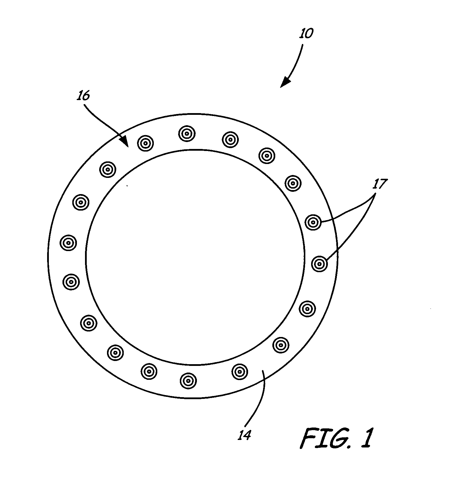
[0021]FIG. 1 is a diagram illustrating an end view of an annular combustor 10 of an aircraft engine having bulkhead section 14. Attached to bulkhead section 14 is fuel manifold assembly 16, which includes a plurality of fuel nozzles 17 (as well as additional components not visible in FIG. 1). It should be noted that an annular combustor 10 is described for purposes of example and not for limitation, and that other types of combustors, such as cylindrical combustors, are also within the intended scope of the present invention.

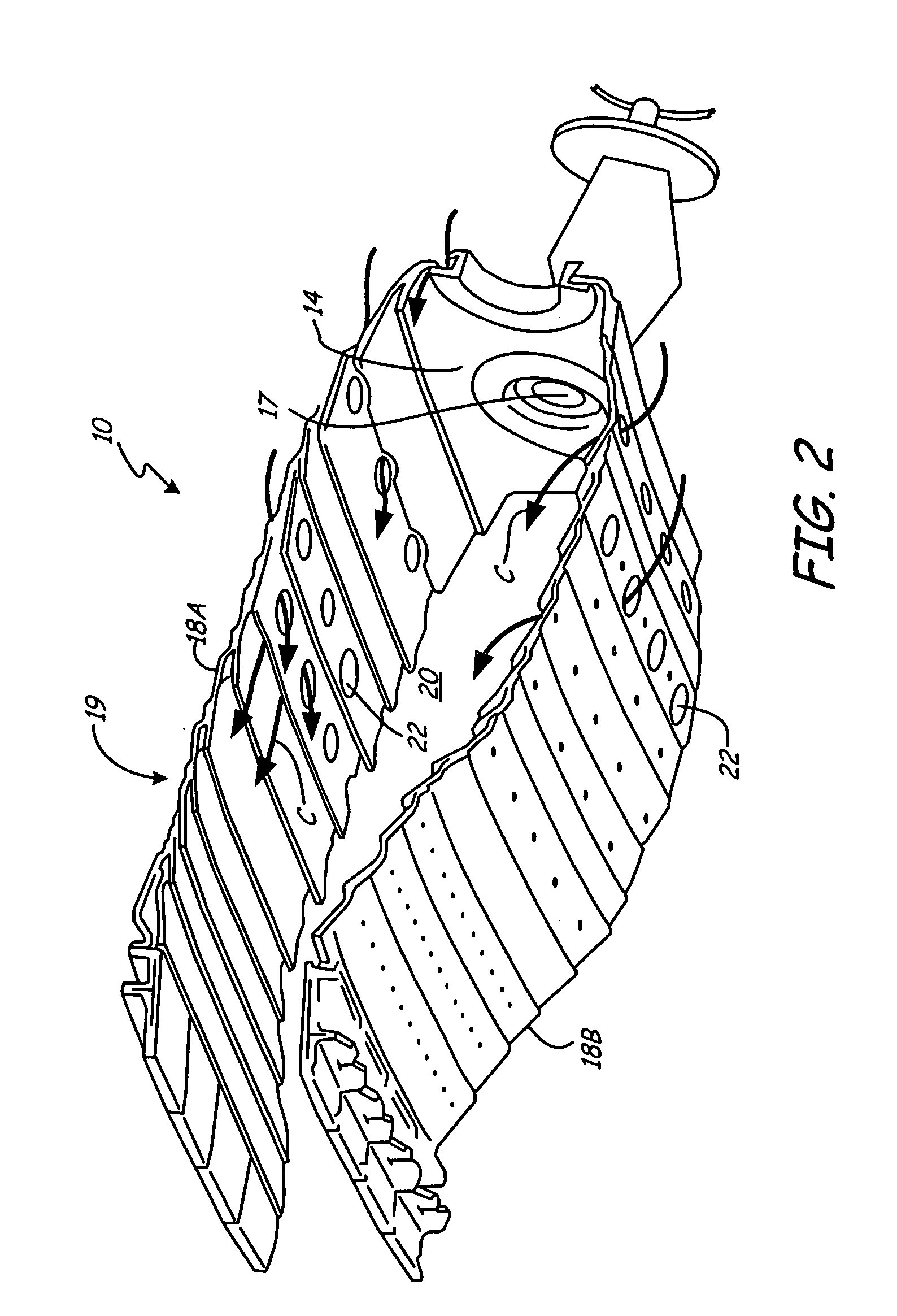
[0022]Combustor 10 is configured to burn a mixture of fuel and air to produce combustion gases. These combustion gases are then delivered to a turbine located downstream of combustor 10 at a temperature which will not exceed an allowable limit at the turbine inlet. Combustor 10, within a limited space, must add sufficient heat and energy to the gases passing through the engine to accelerate their mass enough to produce the desired power for the turbine and thrus...


PUM


Abstract

A method for controlling a temperature distribution within a combustor having a plurality of chamber sections comprising controlling a fuel-to-air ratio in the chamber sections. At least two chamber sections have different fuel-to-air ratios to create a non-uniform temperature distribution within the combustor to reduce thermoacoustic instabilities.

Description

CROSS-REFERENCE TO RELATED APPLICATION(S)[0001]The following application is filed on the same day as the following co-pending application: “FLOW DIVIDER VALVE FOR CONTROLLING A COMBUSTOR TEMPERATURE DISTRIBUTION” by inventors Jeffrey M. Cohen, James B. Hoke, and Stuart Kozola (attorney docket number U73.12-0078). The above application is herein incorporated by reference in its entirety.BACKGROUND OF THE INVENTION[0002]The present invention relates generally to gas turbine engines. More particularly, the present invention relates to a method for controlling thermoacoustic instabilities in a combustor.[0003]Thermoacoustic instabilities arise in gas turbine and aero-engines when acoustic modes couple with unsteady heat released due to combustion in a positive feedback loop. These instabilities can lead to large pressure oscillations inside the combustor cavity, thereby affecting its stable operation and potentially causing structural damage to the combustor components. Two particular e...

Claims


Application Information

Patent Timeline
Patent Type & Authority Applications(United States)
IPC IPC(8): F02C7/26F23M20/00
CPCF23R3/34F23M20/005F23R2900/00014F23R3/50
Inventor HAGEN, GREGORY S.BANASZUK, ANDRZEJMEHTA, PRASHANT G.COHEN, JEFFREY M.PROSCIA, WILLIAM
Owner RTX CORP
Why Eureka
Try Eureka