Hydraulic valve assembly with a pressure compensated directional spool valve and a regeneration shunt valve

a technology of directional spool valve and hydraulic valve, which is applied in the direction of servomotor components, servomotors, servomotor circuits, etc., can solve the problems of energy loss in each of the two valves, affecting the efficiency of the regeneration mode, etc., and achieves constant pressure drop

Inactive Publication Date: 2008-03-27
HUSCO INT INC
View PDF14 Cites 38 Cited by
  • Summary
  • Abstract
  • Description
  • Claims
  • Application Information

AI Technical Summary

Benefits of technology

[0017]In a preferred embodiment, the hydraulic circuit includes a pressure compensation valve connected to the spool valve and maintaining a substantially constant pressure drop between the inlet and a selected one of the first and second workports. In one version o

Problems solved by technology

In addition, the regeneration flow encountered an energy loss in each of the two valves.
Nevertheless, energy losse

Method used


Image

  • Hydraulic valve assembly with a pressure compensated directional spool valve and a regeneration shunt valve
  • Hydraulic valve assembly with a pressure compensated directional spool valve and a regeneration shunt valve
  • Hydraulic valve assembly with a pressure compensated directional spool valve and a regeneration shunt valve

Examples


Embodiment Construction

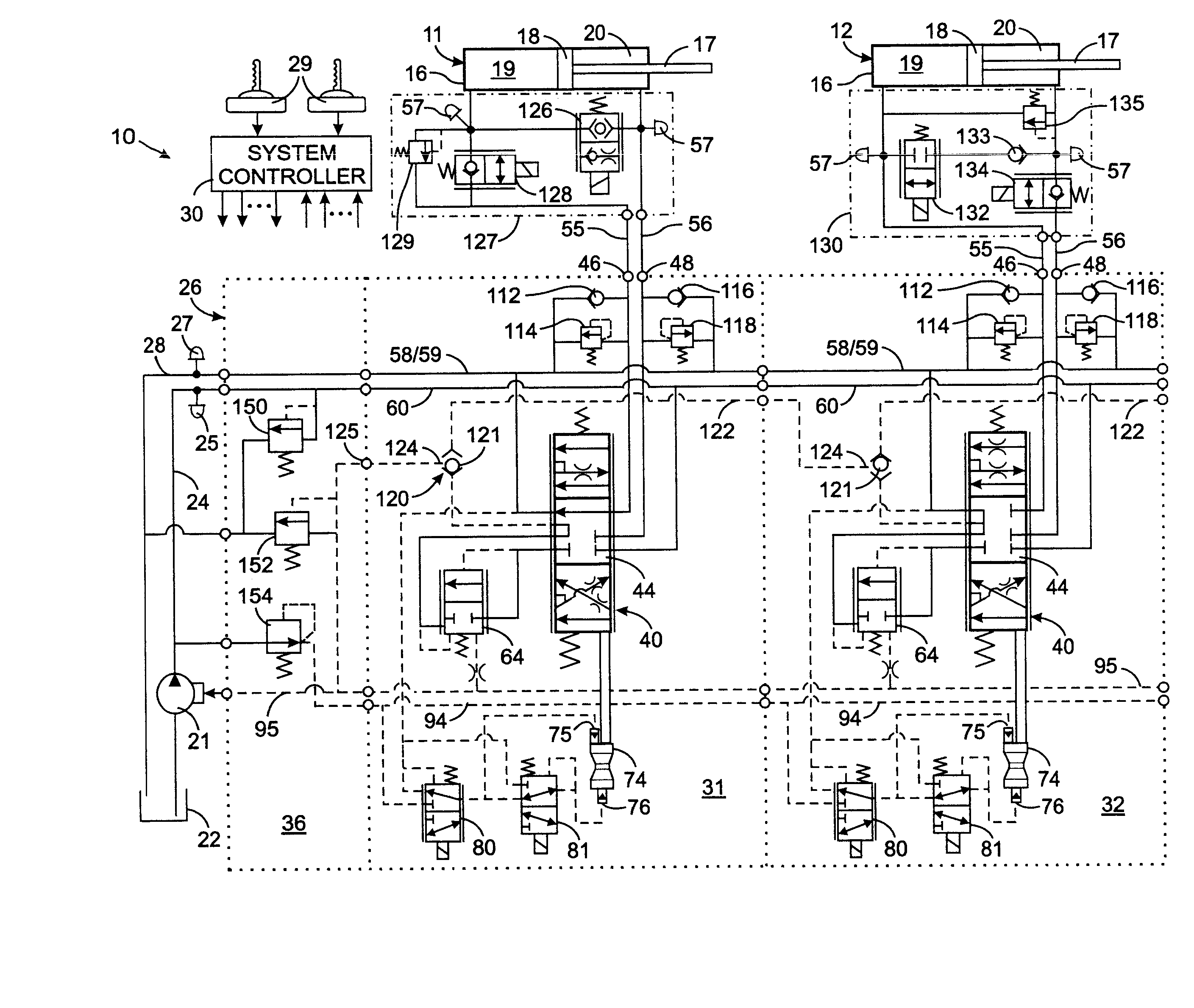
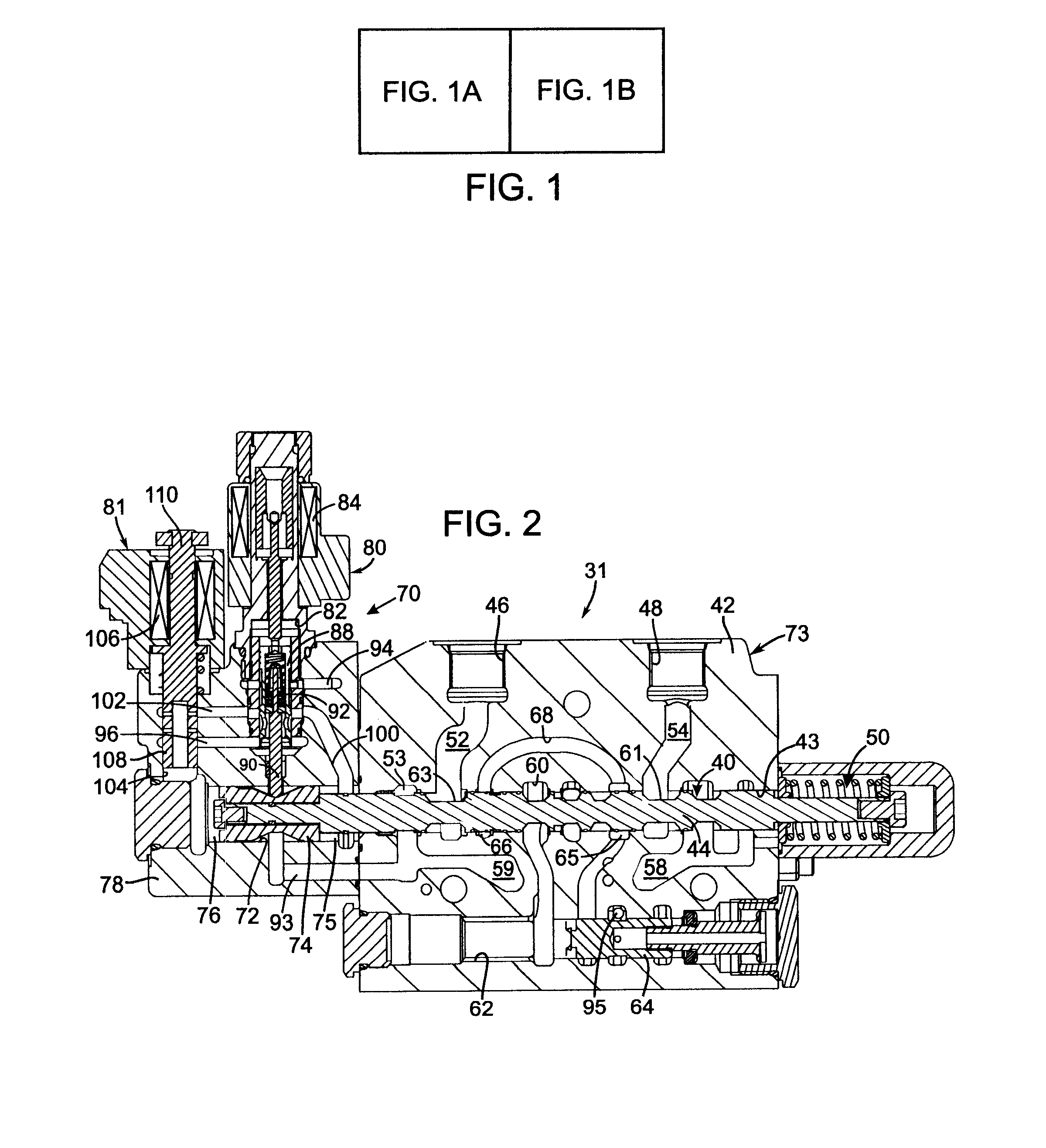
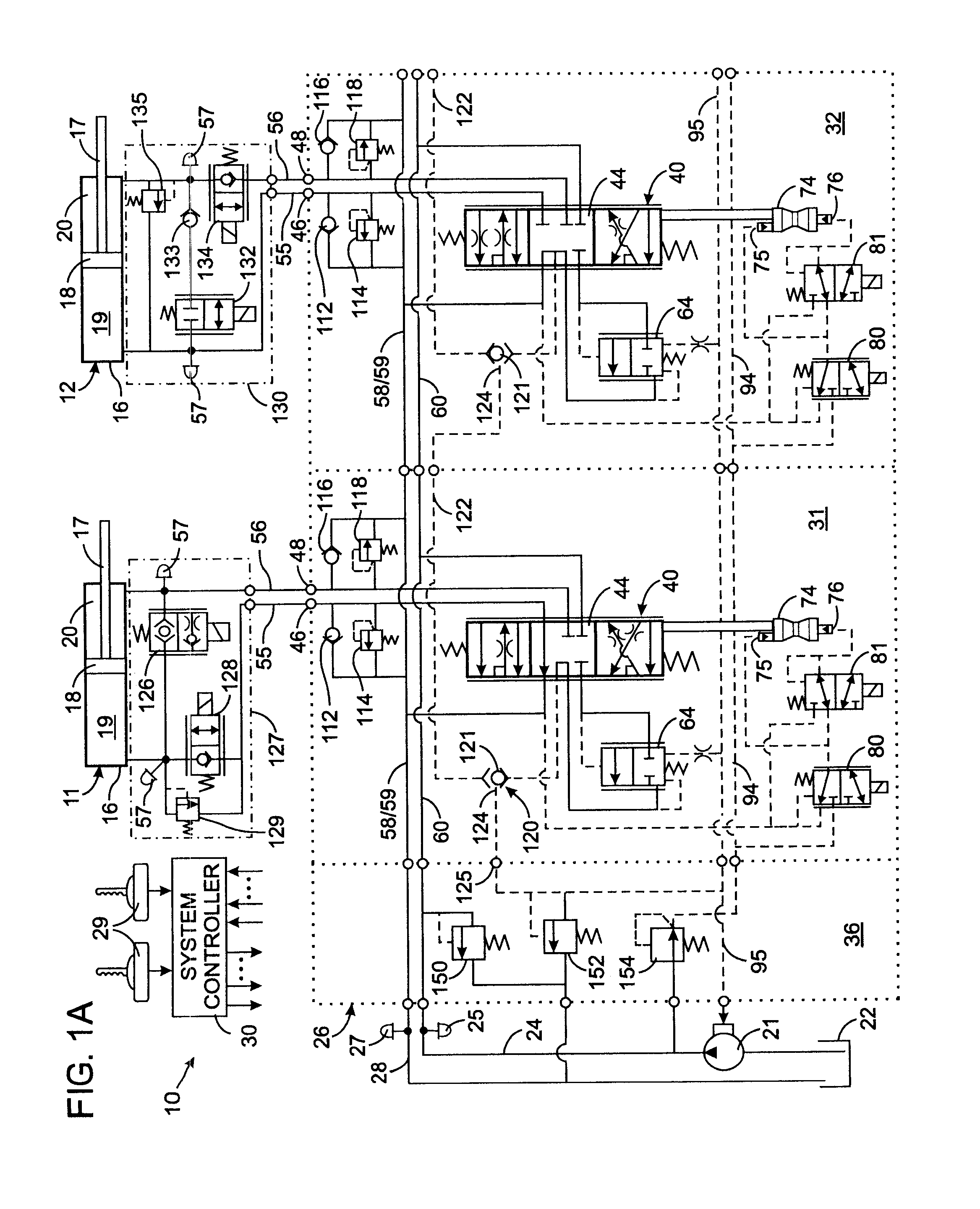
[0020]With initial reference to FIGS. 1A and 1B, a hydraulic system 10 on a machine controls operation of five hydraulic actuators 11, 12, 13, 14, and 15 such as cylinder / piston assemblies. Each hydraulic actuator 11-15 comprises a hydraulic cylinder 16 with a movable piston 18 to which a rod 17 is connected. The piston 18 defines a head chamber 19 and a rod chamber 20 within the cylinder, with first and second ports provided for hydraulic connection respectively to those chambers. It should be understood that the present invention can be used with other types of hydraulic actuators, such as a rotating motor for example.

[0021]The hydraulic system 10 also includes a variable displacement pump 21 which draws fluid from a tank 22 and furnishes that fluid under pressure into a supply conduit 24. The supply conduit is connected to a control valve assembly 26 that controls the flow of fluid to and from the hydraulic actuators 11-15. The fluid returning from the hydraulic actuators flows t...


PUM


Abstract

A hydraulic circuit controls flow of fluid between first and second ports of a hydraulic actuator, such as a cylinder/piston arrangement and each of a supply conduit and a tank return conduit. The hydraulic circuit operates in standard powered operating modes as well as powered and unpowered regeneration modes. In a powered operating mode, a conventional pressure compensated spool valve determines the velocity of the hydraulic actuator. A workport blocking valve connects one workport of the spool valve to the first port and the other workport is connected to the second port. A regeneration shunt valve is directly connected between the first and second ports of the hydraulic actuator. In a regeneration operating mode or a mix of powered and regeneration modes, a combination of the spool valve, the workport blocking valve, and the regeneration shunt valve determines the velocity of the hydraulic actuator.

Description

CROSS-REFERENCE TO RELATED APPLICATIONS[0001]Not ApplicableSTATEMENT REGARDING FEDERALLY SPONSORED RESEARCH OR DEVELOPMENT [0002]Not ApplicableBACKGROUND OF THE INVENTION[0003]1. Field of the Invention[0004]The present invention relates to hydraulic systems that operate actuators, such as cylinder / piston arrangements, and more particularly to hydraulic systems that operate actuators in powered and regenerative modes.[0005]2. Description of the Related Art[0006]A wide variety of machines are operated by a hydraulic system with a plurality of hydraulic actuators, such as cylinder connected one component of the machine and a piston coupled by a rod to another component. The piston divides the interior of the cylinder into two internal chambers and alternate application of hydraulic fluid under pressure to each chamber moves the piston in opposite directions, thereby moving the two components with respect to each other.[0007]In a common hydraulic system, flow of hydraulic fluid to the ...

Claims


Application Information

Patent Timeline
IPC IPC(8): F15B11/08
CPCF15B11/003F15B2211/8636F15B11/0445F15B11/05F15B11/165F15B13/0402F15B13/0433F15B13/0435F15B13/16F15B2211/20546F15B2211/253F15B2211/30555F15B2211/329F15B2211/5059F15B2211/6054F15B2211/6309F15B2211/6313F15B2211/6346F15B2211/7053F15B11/024F15B13/021F15B13/043
Inventor PFAFF, JOSEPH L.STEPHENSON, DWIGHT B.
Owner HUSCO INT INC
Why Eureka
Try Eureka