
Spray-Regulating System Incorporated in Aircraft Anti-Icers

a technology of spray-regulating system and anti-icing device, which is applied in the direction of de-icing equipment, ground installations, transportation and packaging, etc., can solve the problems of too short spray distance of fluid jet, inability to adjust the flow from the nozzle, and too much fluid being used, so as to optimize the spray pattern and maintain constant pressure. , the effect of constant pressure drop

Active Publication Date: 2008-01-24
VESTERGAARD CO AS
View PDF13 Cites 3 Cited by
  • Summary
  • Abstract
  • Description
  • Claims
  • Application Information

AI Technical Summary

Benefits of technology

[0012] According to the invention it is possible to maintain a constant pressure on the upstream side of the nozzle and thereby a constant pressure drop over the nozzle with a variable fluid flow through the nozzle. The constant pressure will optimize the spray pattern without damaging the fluid. With a variable flow it is possible to adjust the amount of fluid sprayed to the amount needed for covering the surface of the aircraft.

Problems solved by technology

In prior art equipment it is common standard to maintain a constant flow rate when anti-icing fluid is sprayed, in order to achieve a constant pressure drop from the fluid pump to the fully opened nozzle, However, this results in too much fluid being used, because the flow from the nozzle cannot be adjusted according to the actual needs.
The occurrence of lower pressure drops over the nozzle would mean too short spray distance of the fluid jet to obtain a satisfactory distribution of fluid on the surface of the aircraft.

Method used


Image

  • Spray-Regulating System Incorporated in Aircraft Anti-Icers
  • Spray-Regulating System Incorporated in Aircraft Anti-Icers

Examples


Embodiment Construction

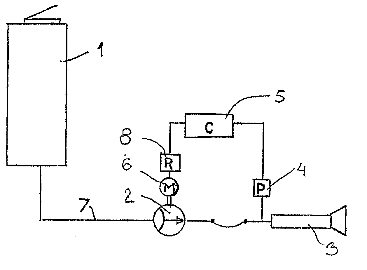
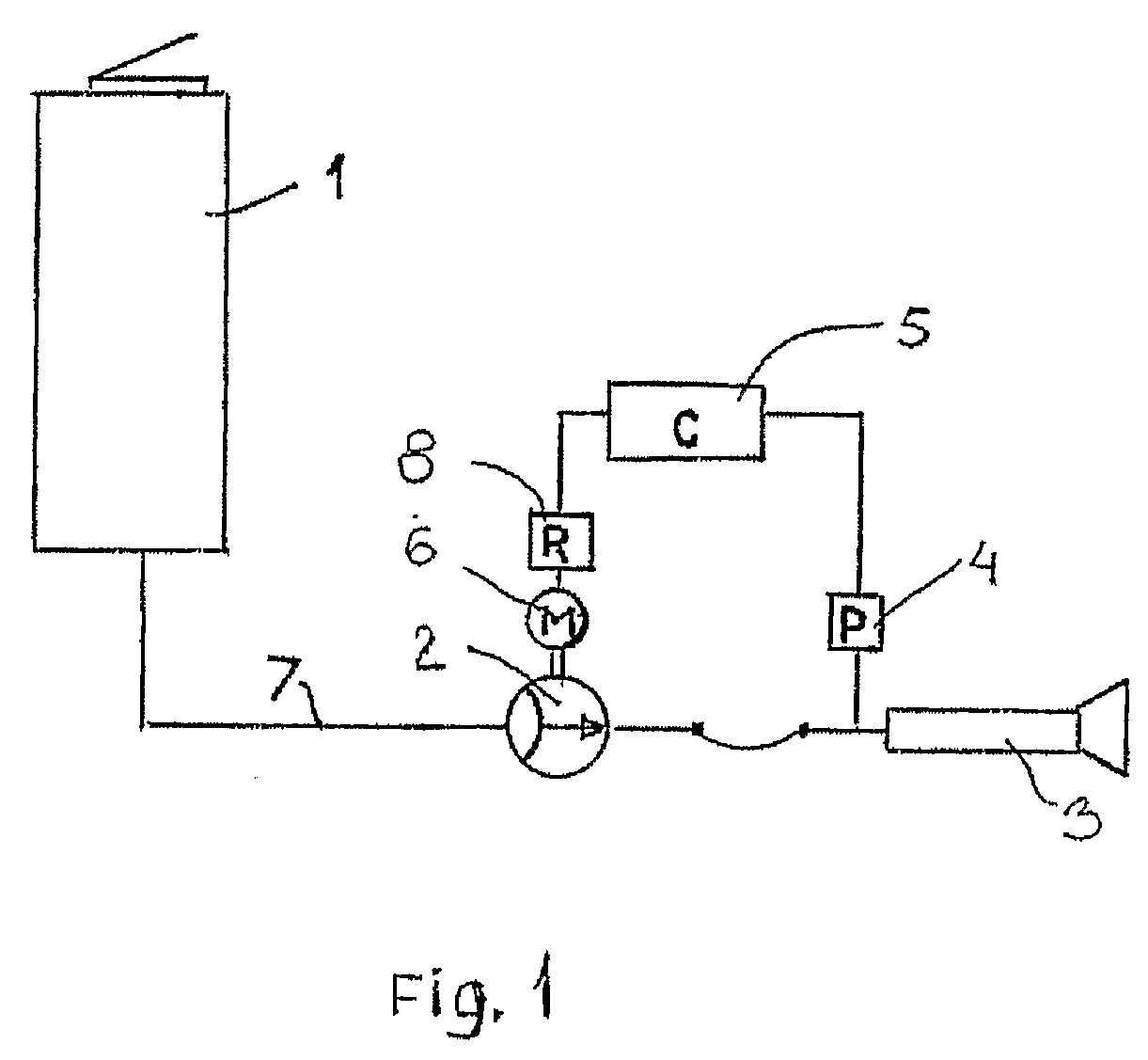
[0019] Referring to FIG. 1 a spray-regulating system according to the invention is illustrated. The system comprises a tank 1 containing anti-icing fluid and being connected to a fluid-diaphragm pump 2 driven by a motor 6. From said pump 2 anti-icing fluid is pumped through a hose or pipeline 7 to the spray nozzle 3 so that it is sprayed onto the surfaces of an aircraft and protects them from building up frozen contaminations on the surface.

[0020] In close proximity to the inlet of the spray nozzle 3, a pressure sensor 4 is mounted in such a way that the inlet pressure is measured and reported to a central control unit 5. Said control unit 5 receives the pressure signal from the sensor 4 and based on the possible difference between the actual pressure and the required pressure a signal is produced and transmitted to a regulating device 8, which will then adjust the speed of the pump motor 6 and thereby influence the fluid flow rate in the pipeline 7.

[0021] In this way it is possib...


PUM


Abstract

The invention relates to de-icing and anti-icing procedures performed on airplanes on the ground, wherein a fluid is sprayed from the boom or arm of a de-icer installation onto the aircraft. A spray-regulating system is incorporated in aircraft anti-icers comprising a tank (1) with anti-icing fluid, a fluid pump (2) with a drive motor (6), and a hose or pipeline (7) between the pump (2) and a spray nozzle (3) located on an elevating boom, arm or operator's platform so that the fluid can be pumped from the tank (1) to the spray nozzle (3), said system further comprising a central control unit (5), a pressure-signal-generating pressure sensor (4) located proximate to the inlet of nozzle (3), and a regulating device (8) for the motor (6) to adjust the motor momentum, wherein a constant pressure upstream of the nozzle (3) and consequently over said nozzle (3) is maintained by said control unit (5) producing a signal calculated on a pressure signal received from the sensor (4) and the pressure required upstream of the nozzle (3), and said signal being transmitted to the regulating device (8), which then adjusts the momentum of the pump motor (6) and thereby adjusts the flow rate and or pressure rate in the pipeline (7).

Description

FIELD OF THE INVENTION [0001] The present invention relates to de-icing and anti-icing procedures performed on airplanes on the ground, wherein a fluid is sprayed from the boom or arm of a de-icer installation onto the aircraft in order to remove or prevent frozen contaminations on the surface. Hereafter the expression de-icing means to remove snow and ice from the aircraft surface, the de-icing being performed by applying a heated low-viscosity fluid. The expression anti-icing is a treatment normally performed after de-icing; the fluid used for anti-icing is a thickened fluid with a higher viscosity. The purpose of the thickened anti-icing fluid is to adhere to the aircraft surface until the aircraft is airborne, to protect the aircraft against precipitation freezing on the surface. BACKGROUND OF THE INVENTION [0002] Such de-icing / anti-icing equipment is widely known from e.g. the patent literature and also from U.S. Pat. No. 4,565,321 “Vehicle for de-icing aircraft” belonging to t...

Claims


Application Information

Patent Timeline
Patent Type & Authority Applications(United States)
IPC IPC(8): B64D15/02B64F5/00
CPCB64F5/0063B64F5/0054B64F5/20B64F5/23B05B12/085
Inventor SVANEBJERG, ELO
Owner VESTERGAARD CO AS
Learn More