Ductless fumehood system

a ductless fumehood and air filter technology, applied in the field of air filtration systems, can solve the problems of ductless fumehoods that have encountered resistance, high installation costs, and high risk of failure of filtration systems

Inactive Publication Date: 2008-03-27
FIPAK RES & DEV
View PDF9 Cites 18 Cited by
  • Summary
  • Abstract
  • Description
  • Claims
  • Application Information

AI Technical Summary

Benefits of technology

[0009] These and other problems associated with conventional ductless fumehoods are addressed by the present invention, which comprises a unique ductless fumehood system comprising at least one ductless fumehood and a remote monitor unit, wherein the at least one ductless fumehood is connected to the remote monitor unit through a communication link, such that the remote monitor unit can monitor one or more ductless fumehoods from a central location and provide alerts to an operator located at the ductless fumehood, or to others located at another location, when a failure is detected at a ductless fumehood.

Problems solved by technology

Furthermore, installation is very fast, since ductless fumehoods require little more than uncrating and initial setup and testing before use.
Despite the significant advantages associated with ductless fumehoods, current ductless fumehoods have nonetheless encountered certain resistance in the marketplace.
This is generally due to concerns about the risk of failure in the filtration system.
This can be of concern when the ductless fumehood is located in a loud and / or otherwise distracting environment, and / or when placed in the hands of poorly trained and / or unreliable personnel.
Furthermore, this can present an administrative problem when the ductless fumehoods are deployed in large numbers and dispersed throughout several laboratories.
In addition to the foregoing, current ductless fumehoods are not modular.
Thus, manufacturers must provide filtration systems in a variety of capacities and dimensions, which multiplies both the number of different fumehood models which must be manufactured as well as their associated manufacturing costs.
Furthermore, the administrative burden associated with managing a large number of these ductless fumehoods can be enormous.
The cost of manufacturing large numbers of different models, and the administrative burdens associated with managing a fleet of such trains, made up of countless different models, can be prohibitive.

Method used


Image

  • Ductless fumehood system
  • Ductless fumehood system
  • Ductless fumehood system

Examples


Embodiment Construction

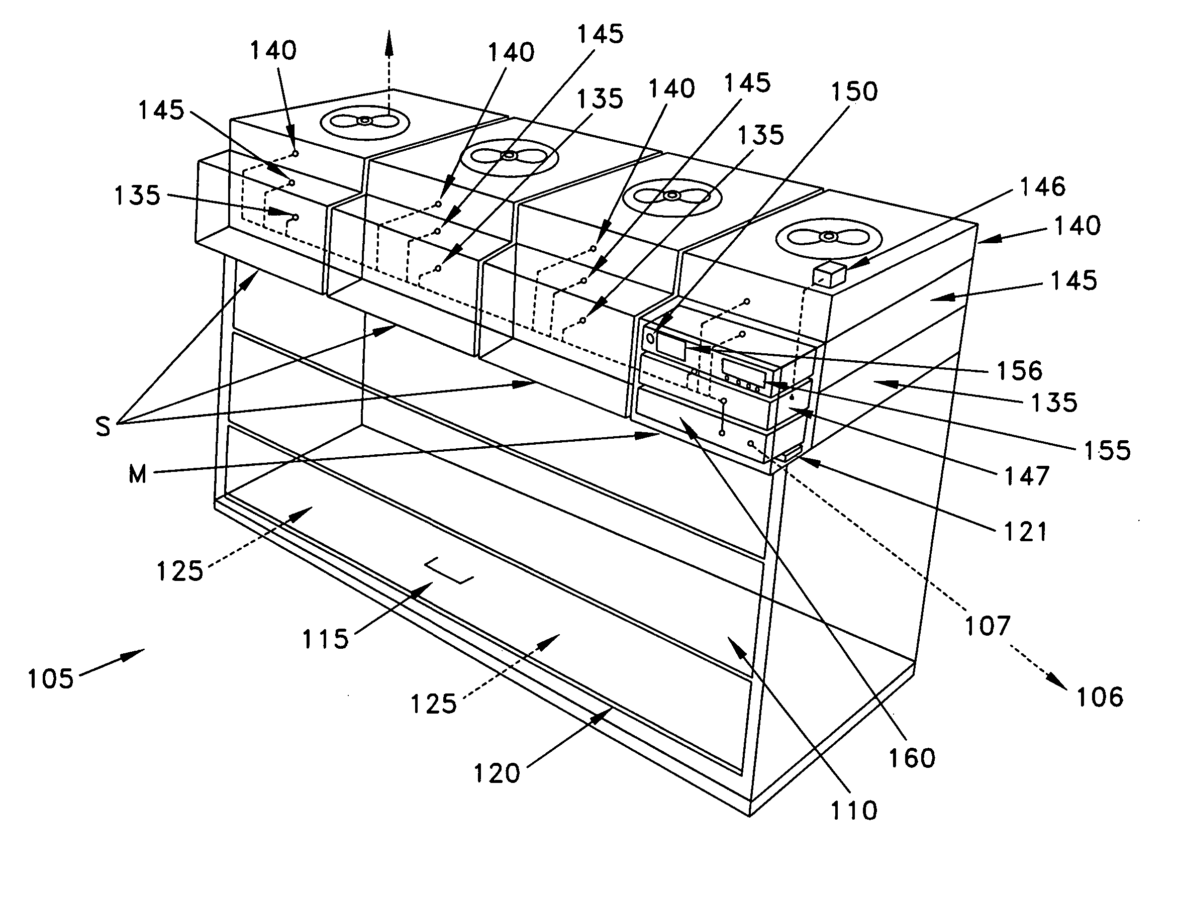
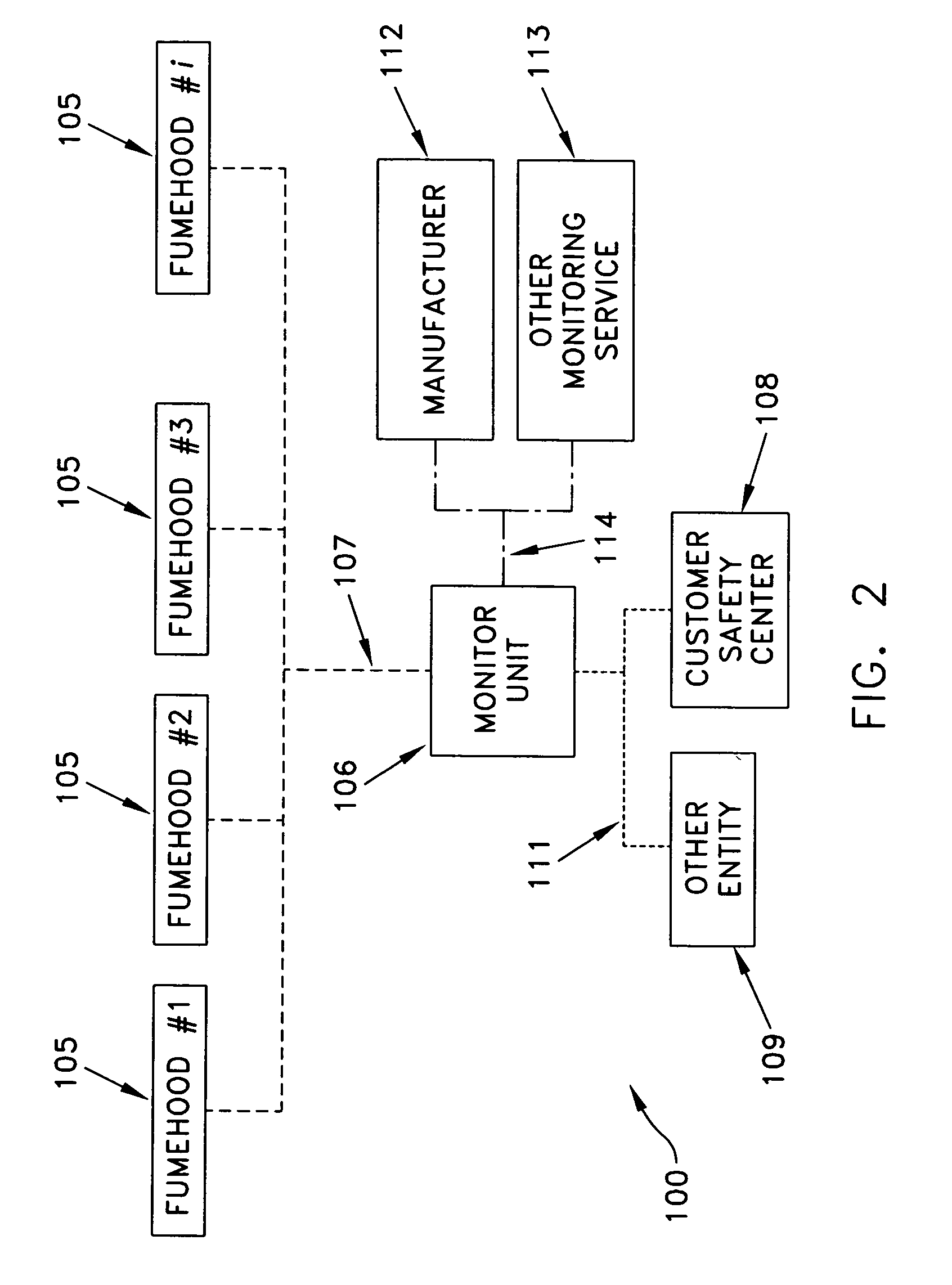
[0099] Looking next at FIG. 2, there is shown a ductless fumehood system 100 formed in accordance with the present invention. Ductless fumehood system 100 generally comprises at least one, and preferably a plurality of, ductless fumehoods 105, and a remote monitor unit 106, wherein ductless fumehoods 105 are connected to remote monitor unit 106 through a communication link 107, such that remote monitor unit 106 can monitor ductless fumehoods 105 from a central location and provide alerts to an operator located at a ductless fumehood when a failure is detected at that ductless fumehood. Communication link 107 may be a “hard-wired” connection (e.g., electrical wire or optical fiber) or a “wireless” connection (e.g., an RF link or a cellular telephone link). Furthermore, communication link 107 may utilize a conventional or proprietary protocol. By way of example but not limitation, communication link 107 may comprise a WIFI connection.

[0100] Additionally, remote monitor unit 106 may a...


PUM

PropertyMeasurementUnit
lengthaaaaaaaaaa
lengthaaaaaaaaaa
pressureaaaaaaaaaa

Abstract

A ductless fumehood system comprising: at least one ductless fumehood comprising a housing; a workspace formed within the housing; a door for selectively closing off the workspace; an air inlet for introducing air into the workspace; a master module for receiving air from the workspace, purging unwanted substances from that air, and then exhausting that filtered air to the ambient room atmosphere; and a slave module for receiving air from the workspace, purging unwanted substances from that air, and then exhausting that filtered air to the ambient room atmosphere; wherein the slave module is in communication with the master module such that the master module central processing unit is capable of (i) controlling the operation of the active elements of the slave module, (ii) detecting a function failure of the slave module, and (iii) activating the master module alarm in the event of a failure within that slave module.

Description

REFERENCE TO PENDING PRIOR PATENT APPLICATION [0001] This patent application claims benefit of pending prior U.S. Provisional Patent Application Ser. No. 60 / 816,211, filed Jun. 23, 2006 by Francois P. Hauville for MODULAR FILTRATION SYSTEM WITHOUT DUCTING, AND EQUIPPED WITH A MANAGEMENT SYSTEM COMPRISING A REMOTE INTERCOMMUNICATION SYSTEM DESIGNED TO ENSURE THE SAFE USE OF DUCTLESS FILTERING FUME HOODS, PRIMARILY IN A LABORATORY SETTING (Attorney's Docket No. FIPAK-6 PROV), which patent application is hereby incorporated herein by reference.FIELD OF THE INVENTION [0002] This invention relates to air filtration systems in general, and more particularly to ductless fumehoods for purging hazardous substances from the air. BACKGROUND OF THE INVENTION [0003] Air filtration systems are used in many situations to purge unwanted substances from the air. Such air filtration systems generally exist in a variety of forms, depending upon their use and function. [0004] One type of air filtration...

Claims


Application Information

Patent Timeline
Patent Type & Authority Applications(United States)
IPC IPC(8): B01D46/46
CPCF24F3/1607B08B15/023F24F3/163F24F11/32F24F11/30F24F11/52F24F8/108
Inventor HAUVILLE, FRANCOIS P.
Owner FIPAK RES & DEV
Why Eureka
Try Eureka