Self aligning non contact shadow ring process kit

a process kit and non-contact technology, applied in the direction of crystal growth process, chemically reactive gas, coating, etc., can solve the problems of particle contamination in the chamber, difficult to control the deposition of sand on the surface of the substrate, and the edge of the wafer is wasted

Inactive Publication Date: 2008-03-27
APPLIED MATERIALS INC
View PDF24 Cites 29 Cited by
  • Summary
  • Abstract
  • Description
  • Claims
  • Application Information

AI Technical Summary

Problems solved by technology

This is highlighted by the recent demands from semiconductor chip manufacturers to minimize edge exclusion on the substrates processed, so that as little of the substrate surface as possible, including the edge of the wafer, is wasted.
One source of particle contamination in the chamber is material deposited at the edge or on the backside of the substrate that flakes off or peels off during a subsequent process.
Substrate edges are typically beveled, making deposition difficult to control over these surfaces.
If a wafer's dielectric layer does not extend to the bevel, metal may be deposited on a silicon bevel and eventually chip or flake, generating unwanted particles in the chamber.
The act of polishing may cause any deposits on the edge and backside surfaces to flake and generate unwanted particles.
One disadvantage with the shadow ring approach is that, by masking a portion of the substrate's perimeter, the shadow ring reduces the overall useful surface area of the substrate.
This problem is made worse if the shadow ring is not accurately aligned with the substrate, and alignment can be difficult to achieve.
However, during the thermal cycling which occurs within a CVD processing chamber, the aluminum rings nonetheless deform, losing the integrity of their shape and therefore compromise their ability to keep particles from depositing on the substrate's edge.
This can change the size of the gap, leading to non-uniformity of deposition across the wafer's edge.
As the aluminum rings expand and contract, material thereon can flake, and create particles which can contaminate the wafer.
Such cleaning increases chamber downtime, reduces throughput and results in higher operating costs.

Method used


Image

  • Self aligning non contact shadow ring process kit
  • Self aligning non contact shadow ring process kit
  • Self aligning non contact shadow ring process kit

Examples


Embodiment Construction

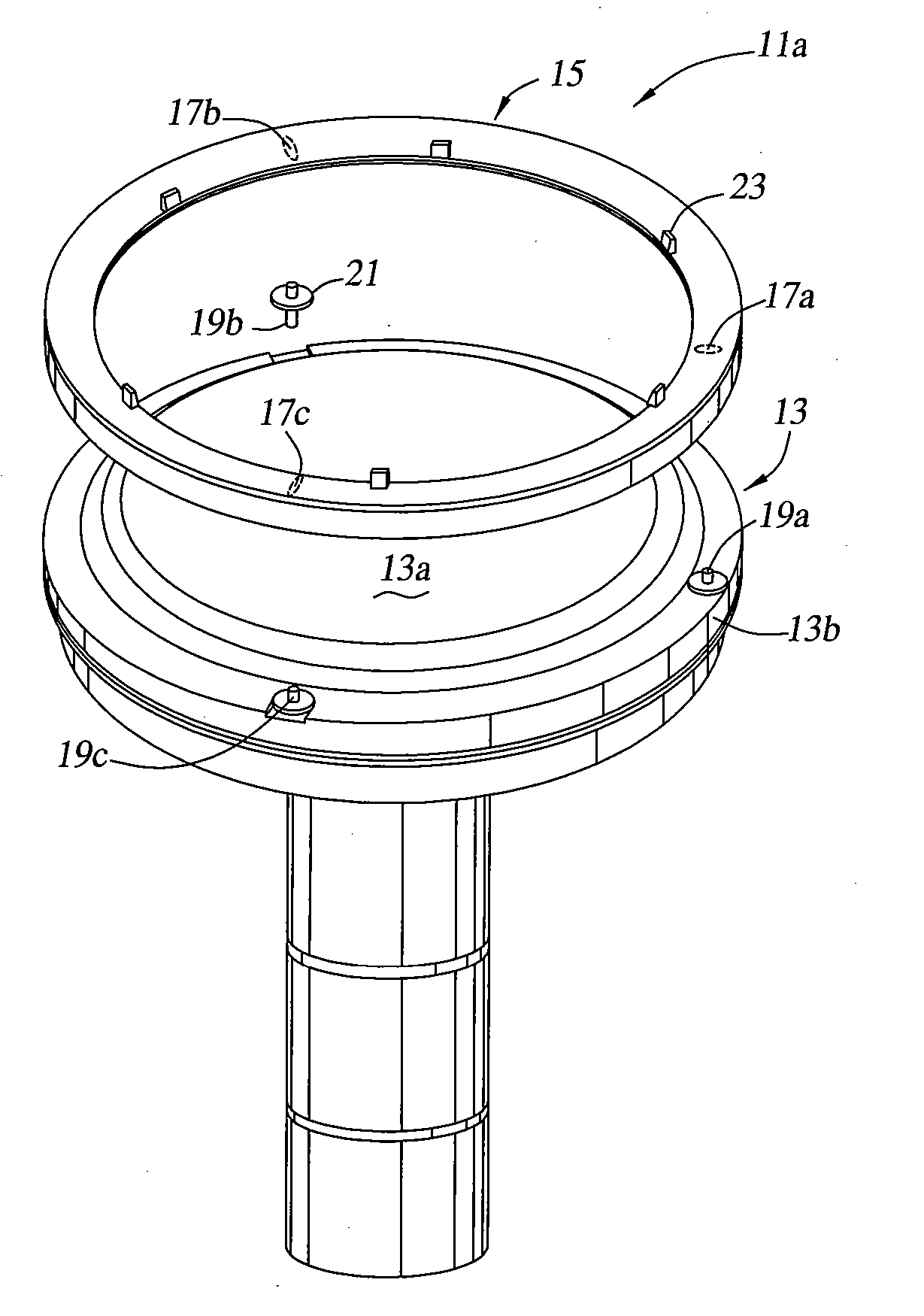
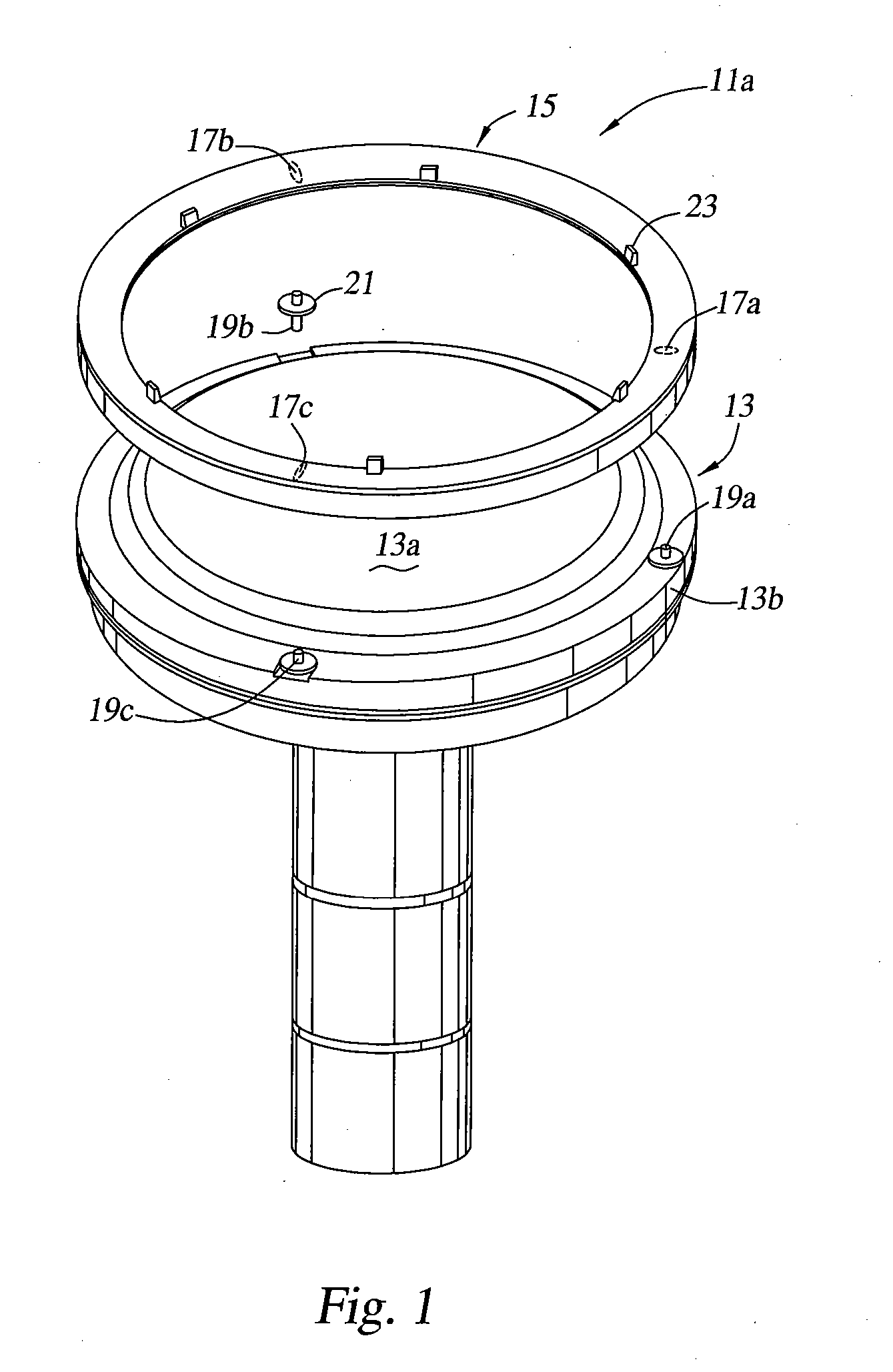
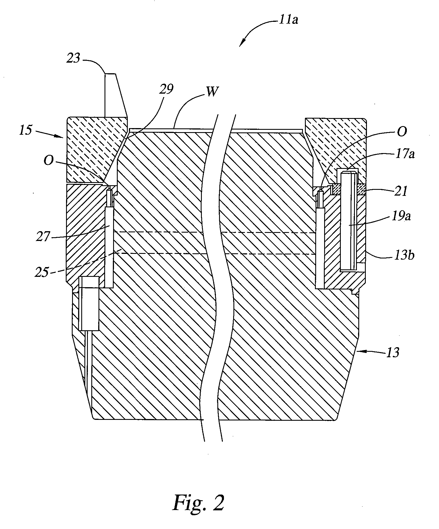
[0028]FIG. 1 is an exploded perspective view of a susceptor 11a. The susceptor 11 a comprises a substrate support 13, adapted for pin and slot coupling with an edge ring, such as purge ring 15. Specifically, the substrate support 13 comprises three pins 19a-c which extend upwardly from the top surface of substrate support 13. The bottom surface of the purge ring 15 comprises three alignment slots 17a-c positioned to interface with the three pins 19a-c. The substrate support 13 comprises a central wafer supporting surface 13a, and the three pins 19a-c are disposed substantially equally spaced around the substrate supporting surface 13a. Each of the slots 17a-c is at least as wide as the corresponding pin 19a-c, and extends radially outward from the center of the substrate supporting surface 13a, in the direction in which the substrate support 13 expands and contracts during thermal cycling.

[0029] The substrate support 13 is preferably made of a metal such as aluminum, as is conventi...


PUM

PropertyMeasurementUnit
temperaturesaaaaaaaaaa
temperatureaaaaaaaaaa
lengthaaaaaaaaaa

Abstract

The invention provides a removable first edge ring configured for pin and recess / slot coupling with a second edge ring disposed on the substrate support. In one embodiment, a first edge ring includes a plurality of pins, and a second edge ring includes one or more alignment recesses and one or more alignment slots for mating engagement with the pins. Each of the alignment recesses and alignment slots are at least as wide as the corresponding pins, and each of the alignment slots extends in the radial direction a length that is sufficient to compensate for the difference in thermal expansion between the first edge ring and the second edge ring.

Description

CROSS-REFERENCE TO RELATED APPLICATIONS [0001] This application is a continuation of co-pending U.S. patent application Ser. No. 10 / 614,992, filed Jul. 7, 2003, which is a continuation of co-pending U.S. patent application Ser. No. 09 / 459,313, filed Dec. 10, 1999. Each of the aforementioned related patent applications is herein incorporated by reference.BACKGROUND OF THE INVENTION [0002] 1. Field of the Invention [0003] The present invention relates to an improved susceptor which inhibits the deposition of process gasses on the edge and backside of a substrate, and which may be easily removed and cleaned. [0004] 2. Description of the Related Art [0005] Chemical vapor deposition (CVD) is one of a number of processes used to deposit thin films of material on semiconductor substrates. To process substrates using CVD, a vacuum chamber is provided with a susceptor configured to receive a substrate. In a typical CVD chamber, the substrate is placed into and removed from the chamber by a r...

Claims


Application Information

Patent Timeline
Patent Type & Authority Applications(United States)
IPC IPC(8): C23C16/458C30B25/12C30B31/14H01L21/205
CPCC23C16/4585C30B31/14C30B25/12C23C16/4586H01L21/68735
Inventor YUDOVSKY, JOSEPHLEI, LAWRENCE C.UMOTOY, SALVADORMADAR, TOMDIXIT, GIRISHTZU, GWO-CHUAN
Owner APPLIED MATERIALS INC
Why Eureka
Try Eureka