
Mechanical percussion mechanism

a percussion mechanism and mechanical technology, applied in the direction of power driven tools, portable percussive tools, construction, etc., can solve the problems of power tools that have to be replaced or repaired, the percussion mechanism cannot be actuated, etc., and achieve the effect of damping the axial motion

Inactive Publication Date: 2008-03-27
ROBERT BOSCH GMBH
View PDF9 Cites 8 Cited by
  • Summary
  • Abstract
  • Description
  • Claims
  • Application Information

AI Technical Summary

Benefits of technology

[0007]The mechanical percussion mechanism according to the invention has the advantage that even in the event of a strong impact, for instance from unintentional or improper handling, the percussion body will not be excessively deflected axially along the drive shaft. This is particularly advantageous whenever the percussion mechanism, for rotary slaving of rotationally supported components, has freely movable or in other words loose slaving elements, such as slaving balls, which could be set free by a strong axial displacement. The capability of axial motion on the part of the percussion body is limited according to the invention by the provision that the percussion mechanism is provided with an axial stop.
[0014]In a preferred embodiment, the stop is embodied as a spring element. The spring element is preferably formed from an elastic material, in particular an elastomer, such as rubber or soft foam. However, the spring element may also be a spring, such as a helical spring or cup spring, of metal or plastic. A spring element as a stop has the advantage that the axial motion of the percussion body is not merely limited by the stop but also damped.
[0016]Because of the annular or disklike embodiment of the stop, particularly as an annular or disklike spring element, the largest possible area of the percussion body comes into contact with the stop when the percussion body meets the stop, and thus the stop can damp the axial motion especially well.
[0017]In an embodiment of the mechanical percussion mechanism of the invention in which the percussion body is prestressed in the direction of the driven shaft via a restoring element, the axial stop prevents excessive axial deflection of the percussion body in the direction of the drive motor. Accordingly, in this embodiment, the stop is located in the region of the drive end of the drive shaft. In the alternative embodiment in which the percussion body is prestressed in the direction of the drive motor, the axial stop prevents an excessive deflection of the percussion body in the direction of the driven shaft. For that purpose, the stop is located in the region of the driven end of the drive shaft.

Problems solved by technology

After that the percussion mechanism can no longer be actuated, and hence the power tool has to be replaced or repaired.

Method used


Image

  • Mechanical percussion mechanism
  • Mechanical percussion mechanism
  • Mechanical percussion mechanism

Examples


Embodiment Construction

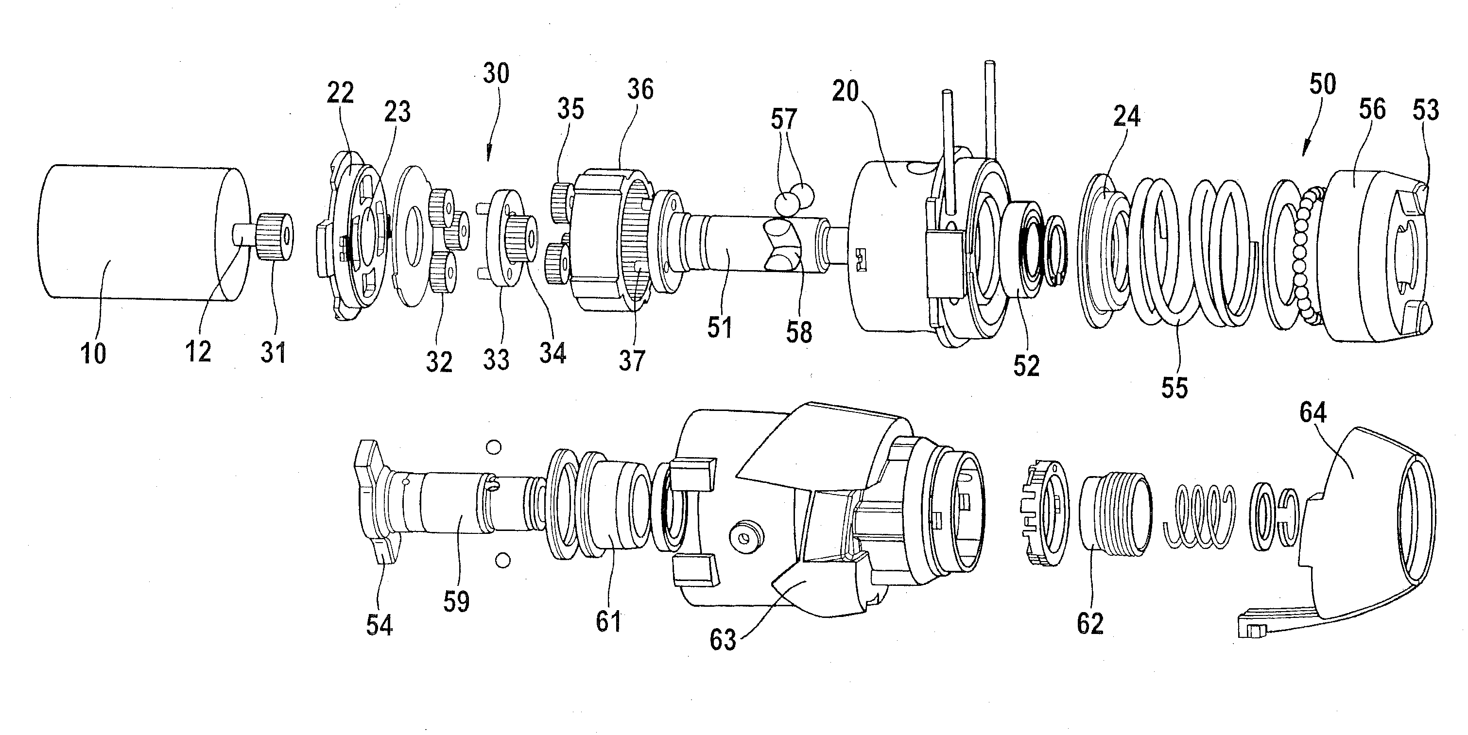
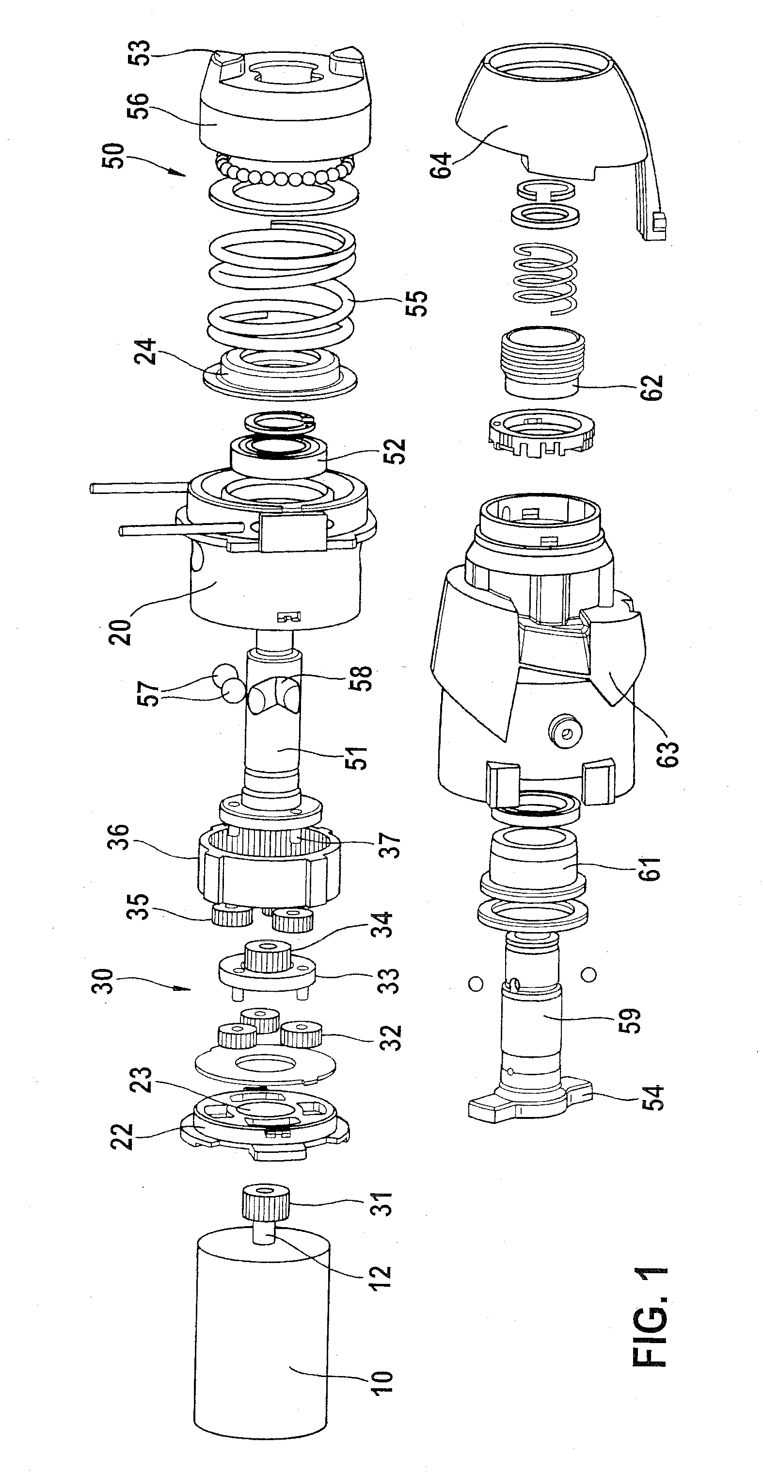
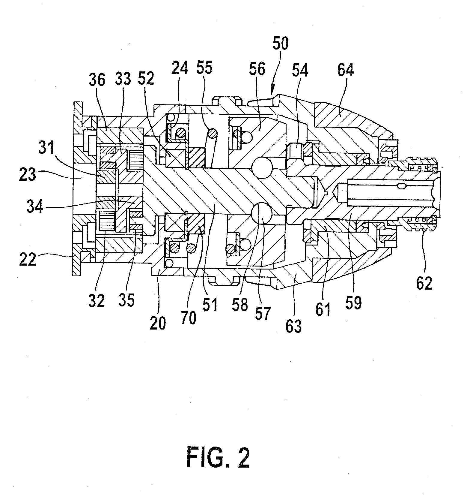
[0020]In the exploded view of FIG. 1, the drive train of a rotary percussion screwdriver is shown, with a mechanical percussion mechanism 50. Hereinafter, only the essential components will be discussed.

[0021]An electric motor 10 (shown schematically) includes an armature shaft 12, on which a gear wheel, serving as a drive pinion 31, is located, in a manner fixed against relative rotation. The drive pinion 31 forms one part of a two-stage planetary gear 30 and drives planet wheels 32 with the first gear stage. The planet wheels 32 roll inside a ring gear 36. As a result, a first sun wheel 33 is rotated, which in turn, via a set of teeth 34, drives further planet wheels 35 of the second gear stage. The planet wheels 35 roll inside the ring gear 36 and drive a second sun wheel 37. The second sun wheel 37 is connected to the drive shaft 51 of the mechanical percussion mechanism 50 in a manner fixed against relative rotation.

[0022]To that end, in FIG. 1, the sun wheel 37 is embodied in ...


PUM


Abstract

A mechanical percussion mechanism for a percussion drive of a tool insert in a handheld power tool has a rotatably supported drive shaft, a percussion body connected to the drive shaft in a manner fixed against relative rotation and supported axially movable relative to the drive shaft, a rotatably supported driven shaft connected to the drive shaft in a manner fixed against relative rotation, the percussion body having drive cams and the driven shaft having drive cams, which drive cams of the percussion body and the driven shaft are bringable into operative connection for a percussion drive of the tool insert, and an axial stop provided for the percussion body.

Description

CROSS-REFERENCE TO A RELATED APPLICATION[0001]The invention described and claimed hereinbelow is also described in German Patent Application DE 202006014850.7 filed on Sep. 27, 2006. This German Patent Application, whose subject matter is incorporated here by reference, provides the basis for a claim of priority of invention under 35 U.S.C. 119(a)-(d).BACKGROUND OF THE INVENTION[0002]The invention relates to a mechanical percussion mechanism for a handheld power tool, in particular a rotary percussion screwdriver.[0003]From the prior art, such as German Patent Disclosure DE 10 2004 032 789 A1, rotary percussion screwdrivers with a V-groove rotary percussion mechanism are known. In general, rotary percussion mechanisms convert the continuous power output of the drive motor into a percussionlike rotary pulse, and the energy output of the motor is temporarily stored in a mass and abruptly delivered to the tool insert, such as a drill bit, by means of a pulse of high power intensity. In...

Claims


Application Information

Patent Timeline
Patent Type & Authority Applications(United States)
IPC IPC(8): E02D7/02
CPCB25D11/08B25B21/02
Inventor YEOH, SIM TEIKLEE, SIEW YUENLUTZ, MANFREDNG, CHIN AUN
Owner ROBERT BOSCH GMBH
Learn More