Sheet conveying system, as well as image forming apparatus and sheet conveying apparatus thereof

a sheet conveying and sheet technology, applied in the direction of thin material processing, article separation, printing, etc., can solve the problems of deteriorating image formed on the sheet, looping of sheets being conveyed, physical damage to sheets, etc., to achieve smooth control of acceleration, deceleration, or stop of conveyan

Inactive Publication Date: 2008-03-27
CANON KK
View PDF5 Cites 11 Cited by
  • Summary
  • Abstract
  • Description
  • Claims
  • Application Information

AI Technical Summary

Benefits of technology

[0011]The present invention provides a sheet conveying system in which when a sheet is passed from a sheet conveying apparatus to another, each having a sheet conveyance controller, the receiving apparatus can smoothly control acceleration, deceleration, or stop of conveyance of the sheet, as well as an image forming apparatus and sheet conveying apparatus thereof.
[0013]Thus, when a sheet is passed through a plurality of sheet conveying apparatuses of which each has a sheet conveyance controller, one of the sheet conveying apparatuses that receives the sheet can smoothly control acceleration, deceleration, or stop of conveyance of the sheet. Consequently, damage to sheets being conveyed, such as bends and tears of sheets, can be prevented.

Problems solved by technology

In such an apparatus, if the conveying velocity of the conveying roller pair on the downstream side is lower than that on the upstream side, a sheet being conveyed can be looped and physical damage to the paper, such as a bend, can be caused.
However, the use of the one-way clutch for the conveying roller pair causes roller traces left on the surface of the sheet, which deteriorates image formed on the sheet.
That is, the technique does not consider controlling separation of the conveying roller pair on the upstream side, in the case where a plurality of sheet conveying apparatuses each having a controller and a conveying roller pair are coupled together.
However, when the various types of sheet conveying apparatuses, each having sheet conveyance control means, are coupled together in various combinations, it is difficult to control each of the conveying roller pairs in these sheet conveying apparatuses to bring acceleration and deceleration of their conveying velocities into synchronization with each other.

Method used


Image

  • Sheet conveying system, as well as image forming apparatus and sheet conveying apparatus thereof
  • Sheet conveying system, as well as image forming apparatus and sheet conveying apparatus thereof
  • Sheet conveying system, as well as image forming apparatus and sheet conveying apparatus thereof

Examples


Embodiment Construction

[0034]The present invention will now be described in detail with reference to the drawings showing preferred embodiments thereof. It should be noted that the relative arrangement of the components, the numerical expressions and numerical values set forth in these embodiments do not limit the scope of the present invention unless it is specifically stated otherwise.

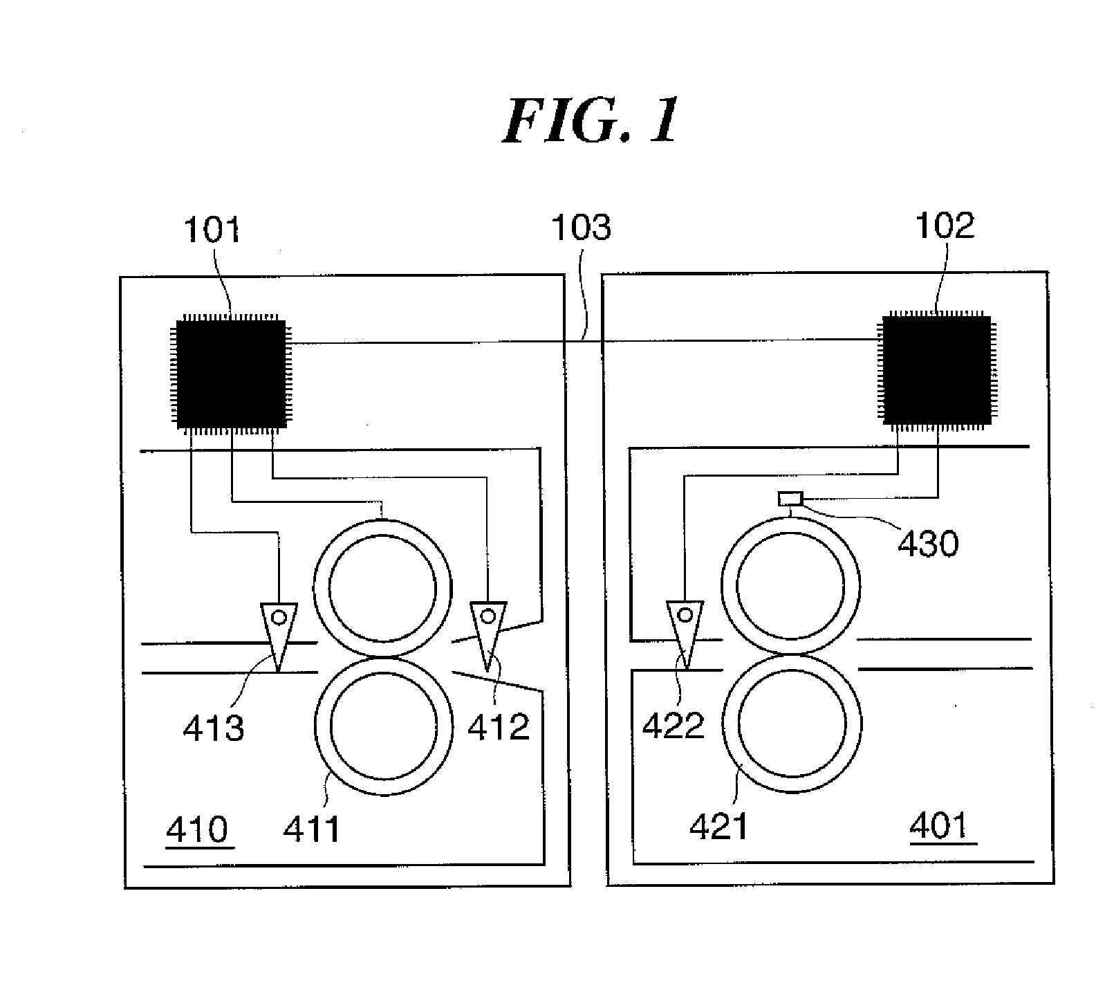
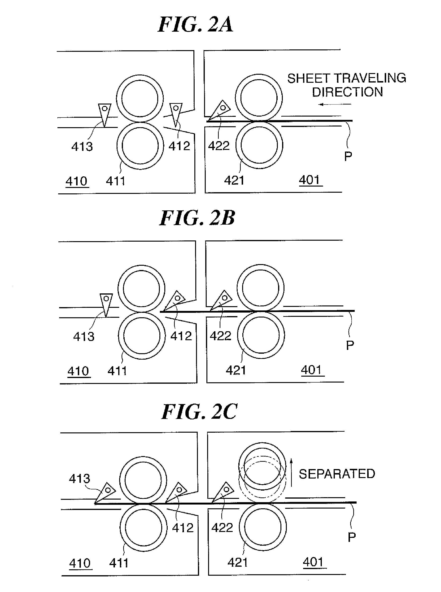
[0035]FIG. 1 is a diagram illustrating a sheet conveying system according to a first embodiment of the present invention. FIGS. 2A to 2C are diagrams illustrating an operation of the sheet conveying system shown in FIG. 1. FIG. 3 is a timing chart showing an operation for passing a sheet.

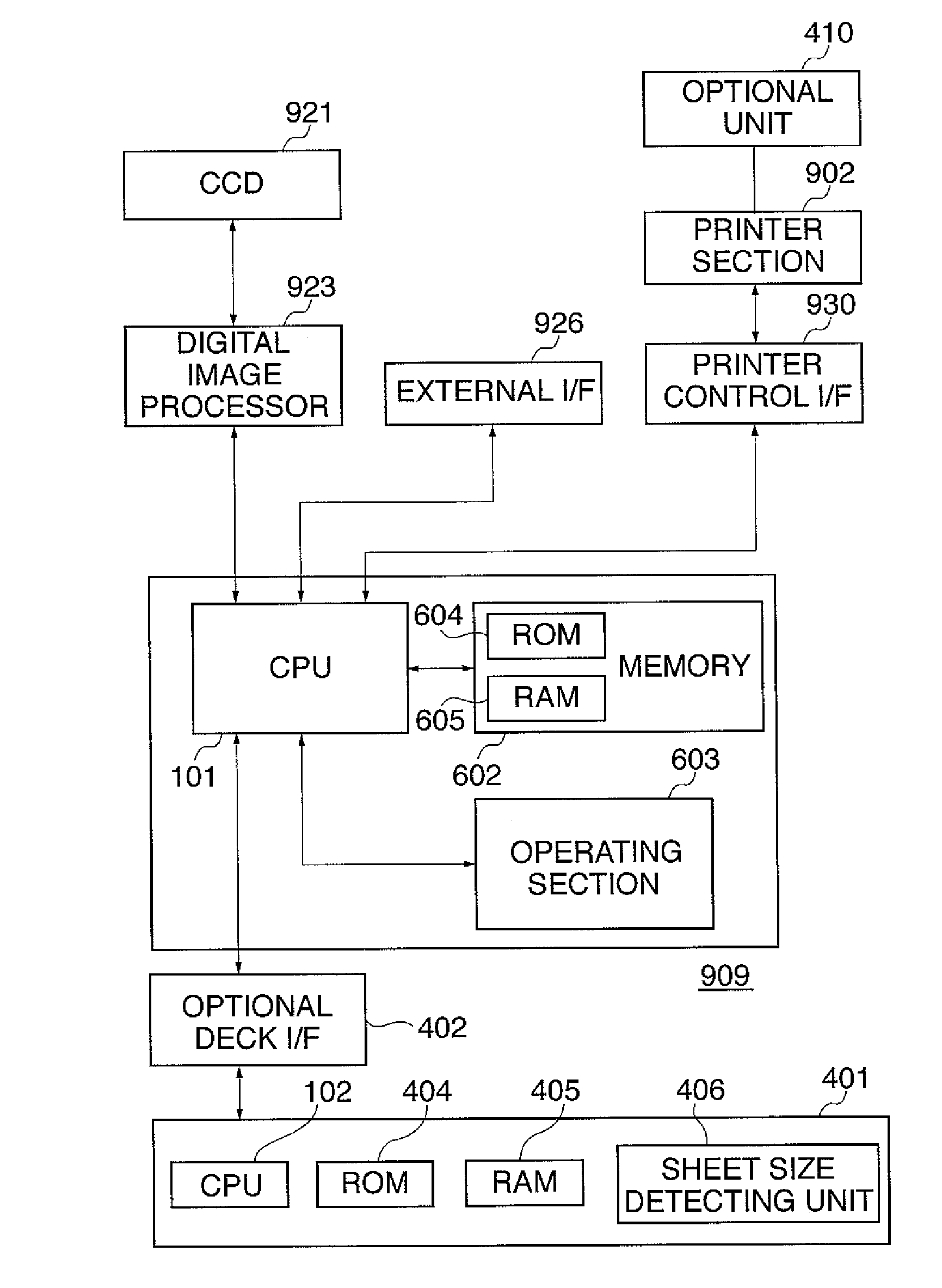
[0036]FIG. 4 is a schematic diagram showing a color image forming apparatus coupled with an optional paper feed apparatus. FIG. 5 is a block diagram illustrating connection between a controller of a printer section and a reader section, all of which are included in the color image forming apparatus shown in FIG. 4. FIG. 6 is a schematic cr...


PUM


Abstract

A sheet conveying system in which when a sheet is passed from a sheet conveying apparatus to another, each including a sheet conveyance controller, the receiving apparatus can smoothly control acceleration, deceleration, or stop of conveyance of the sheet. A first sheet conveying device includes a first conveying roller pair to nip and convey a sheet, a releasing mechanism to release nipping of the sheet by the first conveying roller pair, and a first controller to control the first conveying roller pair and the releasing mechanism. A second sheet conveying device includes a second conveying roller pair to nip and convey the sheet conveyed by the first sheet conveying device, a second controller to control the second conveying roller pair, and a detecting device to detect position of a sheet. In response to the detection by the detecting device, the second controller causes the releasing mechanism to release the nipping of the sheet by the first conveying roller pair.

Description

BACKGROUND OF THE INVENTION[0001]1. Field of the Invention[0002]The present invention relates to a sheet conveying system, as well as an image forming apparatus and a sheet conveying apparatus thereof, more particularly, to a sheet conveying system in which multiple sheet conveying apparatuses, each having a conveying roller pair which conveys sheets, are coupled together as in a configuration in which an image forming apparatus such as a copying machine or a printer is coupled with an optional apparatus, as well as an image forming apparatus and a sheet conveying apparatus thereof.[0003]2. Description of the Related Art[0004]In some sheet conveying apparatuses in which a plurality of conveying roller pairs nip and convey a sheet, a conveying roller pair on the downstream side may control acceleration, deceleration, or stop the conveyance of the sheets.[0005]In such an apparatus, if the conveying velocity of the conveying roller pair on the downstream side is lower than that on the ...

Claims


Application Information

Patent Timeline
IPC IPC(8): B65H7/02B41F13/00
CPCB65H29/12B65H2402/10B65H2801/12B65H2801/09B65H2511/22B65H2511/20B65H2404/1442B65H2404/14B65H2220/09B65H2220/01B65H2220/02B65H2220/11
Inventor ONO, TORUOKAMOTO, KIYOSHIMATSUI, NORIAKI
Owner CANON KK
Why Eureka
Try Eureka