
Pushing block and and a handler with the pushing block

a technology of pushing block and handler, which is applied in the direction of individual semiconductor device testing, semiconductor/solid-state device testing/measurement, instruments, etc., can solve the problems of packaged chips deviating from the socket, difficult to take corrective action, and picker malfunction

Inactive Publication Date: 2008-03-27
MIRAE CORPORATION
View PDF2 Cites 8 Cited by
  • Summary
  • Abstract
  • Description
  • Claims
  • Application Information

AI Technical Summary

Benefits of technology

The present invention provides a pushing block for a handler that can release a packaged chip from a test tray without interfering with a picker and a handler equipped with the pushing block. The pushing block has a simplified structure and a compact design. The assembly that moves the pushing block vertically is easy to install and maintain. The positioning of the pushing block under the test tray allows for corrective action when malfunction of the picker occurs. The whole bottom of the first plate is supported and pushed upwards, thus enabling all the pushing pins to open the latches uniformly at the same time. The invention also provides a handler, a test unit, a loading stacker, an unloading stacker, an exchanging unit, a picker, and a pushing block.

Problems solved by technology

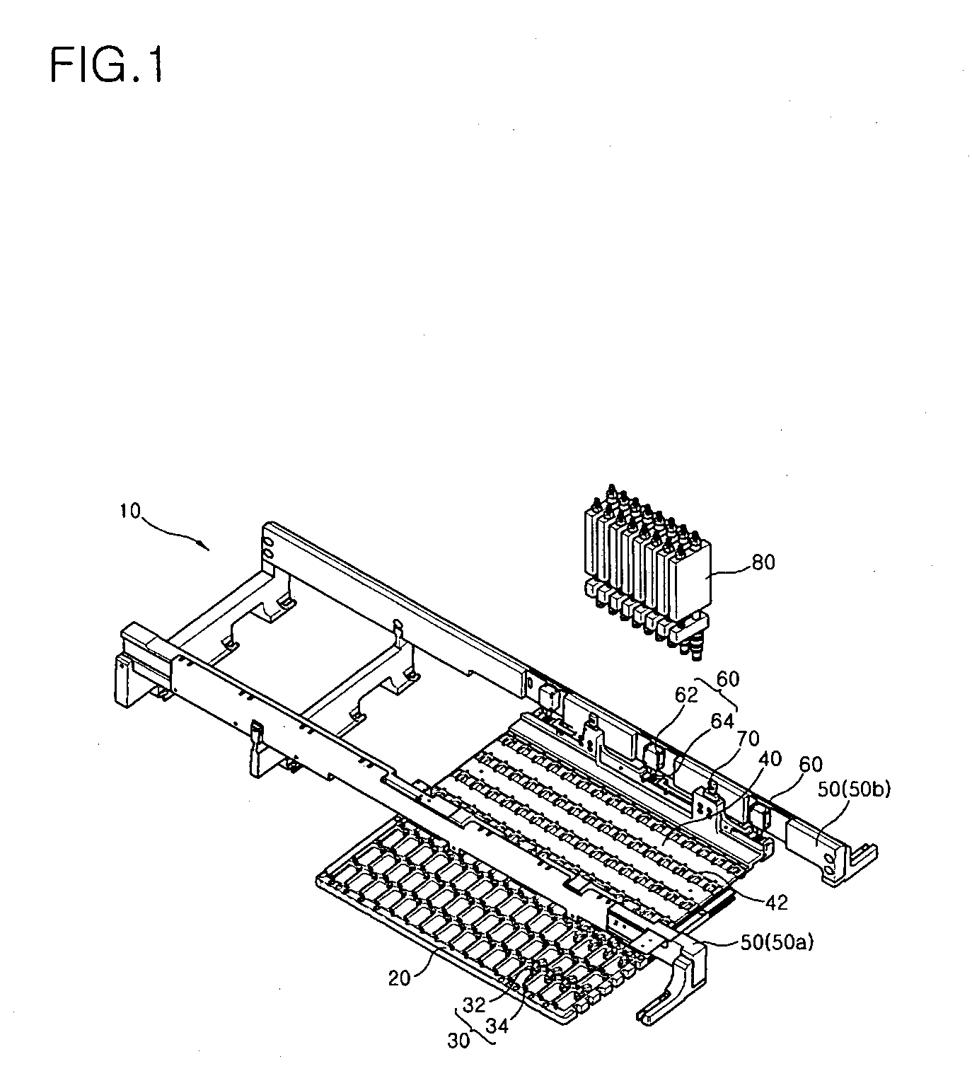
This makes it difficult to take corrective action when the picker fails to function properly, such as deviation of the packaged chip from the socket, and wrong insertion of the packaged chip into the socket.
Furthermore, positioning of the pushing block 10 between the picker and the test tray causes interference between the picker and the pushing block, thus making the packaged chip deviate from the socket.
This causes a malfunction of the picker.
As a result, the picker fails to pick up the packaged chip.

Method used


Image

  • Pushing block and and a handler with the pushing block
  • Pushing block and and a handler with the pushing block
  • Pushing block and and a handler with the pushing block

Examples


Embodiment Construction

[0040]Reference will now be made in detail to the preferred embodiments of the present invention, examples of which are illustrated in the accompanying drawings.

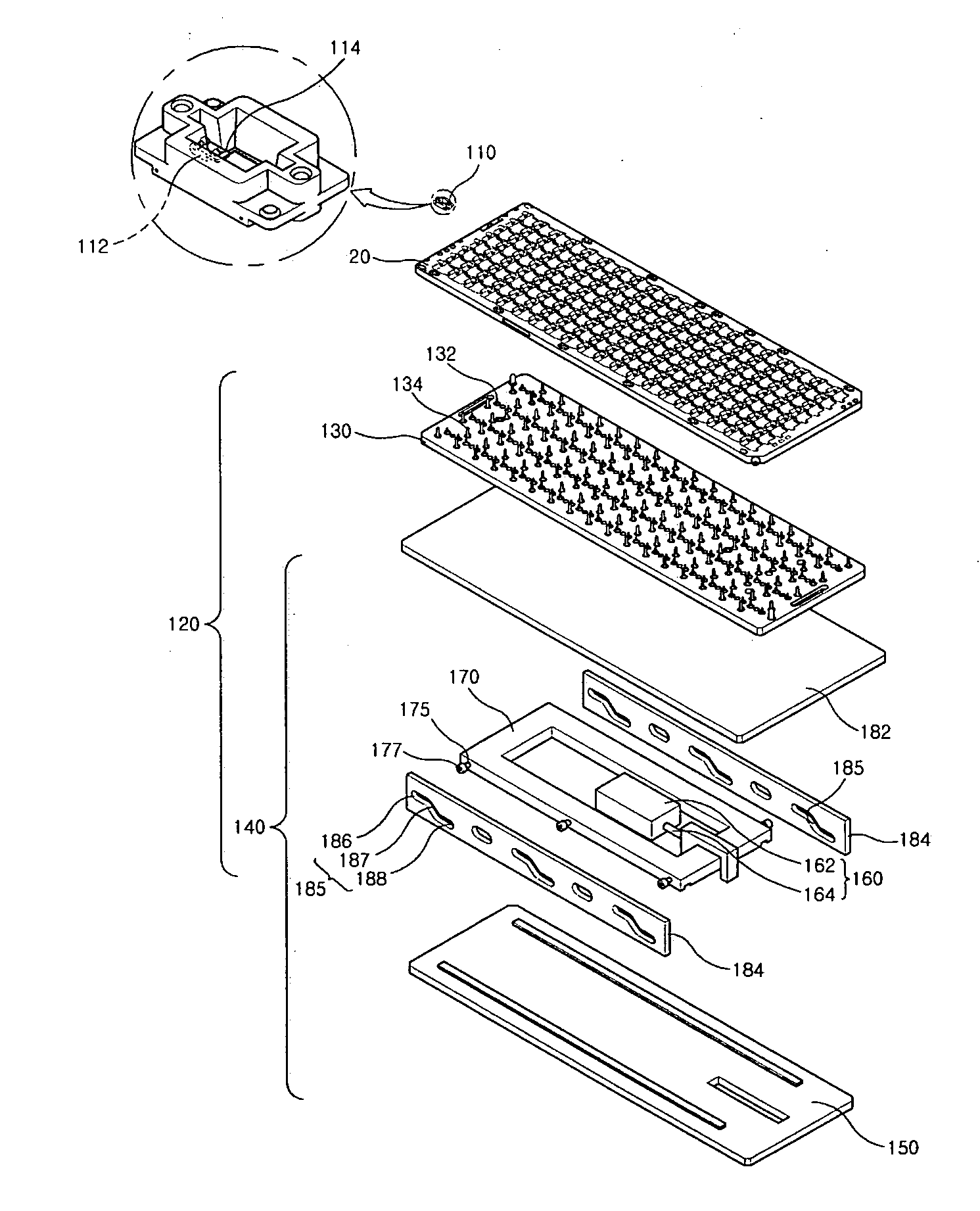
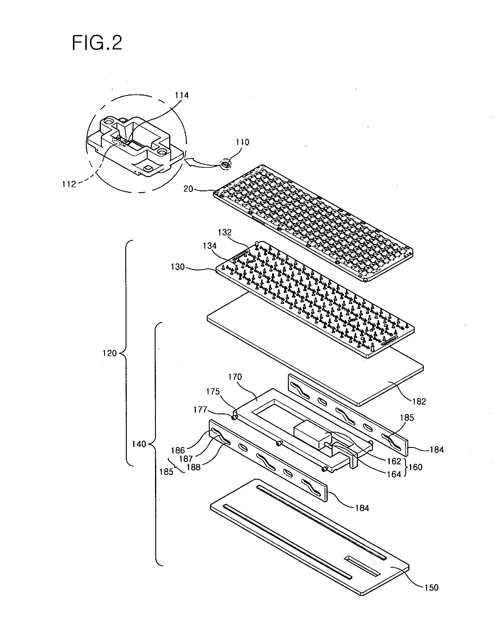
[0041]FIG. 2 is a perspective exploded view illustrating a pushing block 120 and a test tray which are for use in a handler, according to an embodiment of the present invention and a test tray. FIG. 3 is a perspective comprehensive view illustrating the pushing block 120 of FIG. 2.

[0042]The handler inserts packaged chips into a test tray and transfers the test tray containing the packaged chips to a tester. The handler unloads tested packaged chips from sockets of the test tray.

[0043]As shown in FIGS. 2 and 3, the pushing block 120 is provided under the test tray 20.

[0044]The test tray 20 is a jig which serves to contain the packaged chips E for transfer. A plurality of sockets 110 is provided in rows and columns on the test tray 20. The socket 110 includes a latch which holds inserted packaged in place. The latch includes a...


PUM


Abstract

Provided is a pushing block for use in a handle and a handler equipped with the pushing block. The pushing block includes pushing pins, provided under the test tray, each pushing the latch upwards from under the test tray to enable the latch to release the packaged chip, a first plate on which the pushing pins are provided, and an assembly changing horizontal motion into vertical motion to move the first plate vertically. Positioning of the pushing block under the test tray prevents interference between the pushing block and the picker during loading and unloading and makes it convenient to take corrective action when malfunction of the picker occurs.

Description

CROSS REFERENCE TO RELATED APPLICATIONS[0001]This application claims priority from Korean Patent Application No. 10-2006l -0092269, filed on Sep. 22, 2006, the disclosure of which is incorporated herein in its entirety by reference.BACKGROUND OF THE INVENTION[0002]1. Field of the Invention[0003]The present invention relates to a pushing block which enables a latch to hold in place or release a packaged chip in a socket of a test tray when loading or unloading the packaged chip upon and from the socket and a handler equipped with the pushing block.[0004]2. Description of the Background Art[0005]At the conclusion of a packaging process, a handler puts packaged chips through a series of environmental, electrical, and reliability tests. These tests vary in type and specifications, depending on the customer and use of the packaged devices. The tests may be performed on all of the packages in a lot or on selected samples.[0006]The handler puts packaged chips into a test tray and supplies ...

Claims


Application Information

Patent Timeline
Patent Type & Authority Applications(United States)
IPC IPC(8): H01R13/62G01R31/26
CPCG01R31/2893G01R31/26H01L22/00
Inventor AHN, JUNG-UGKIM, SUN-HWALCHOI, WAN-HEEHUR, JUNG
Owner MIRAE CORPORATION
Learn More