Reticle for telescopic gunsight and method for using cross reference to related application

a technology of telescopic gunsights and cross references, applied in the field of telescopic, can solve the problems of difficult or slow use of scopes, limited usefulness of telescopic sights disclosed in the aforementioned prior art patents, and complex mental or physical manipulation, and achieve the effect of promoting shooter confiden

Inactive Publication Date: 2005-01-13
SMITH THOMAS D III
View PDF13 Cites 92 Cited by
  • Summary
  • Abstract
  • Description
  • Claims
  • Application Information

AI Technical Summary

Benefits of technology

[0034] The specific and precise configuration and positioning of the range marker and wind bar lines enables the shooter to mentally compute the range to the target and allow for bullet drop, wind drift, gyroscopic effects, up-hill or down-hill angle shots and target lead. With modest practice, a typical shooter can learn to accomplish these tasks within in a

Problems solved by technology

The telescopic sights disclosed in the aforementioned prior art patents are often of limited usefulness insofar as they do not address many of the several factors that need to be considered in the accurate aiming of a rifle under field conditions.
Older reticle systems often require that the shooter look away from the target in order to make compensating adjustments and almost always require complicated mental or physical manipulations.
Some of these designs

Method used


Image

  • Reticle for telescopic gunsight and method for using cross reference to related application
  • Reticle for telescopic gunsight and method for using cross reference to related application
  • Reticle for telescopic gunsight and method for using cross reference to related application

Examples


Embodiment Construction

[0047] (For The Purposes of Clarification Only)

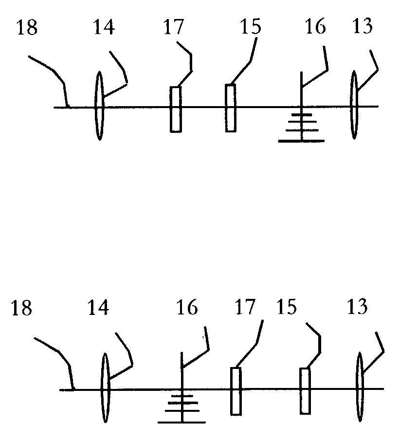
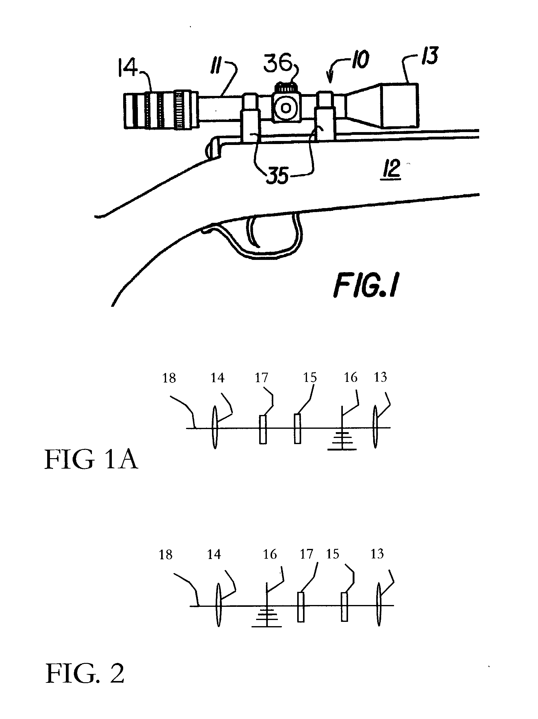
[0048] Referring to FIGS. 1-3, a telescopic sight 10, embodying this invention is shown attached by a suitable mount 35 to a gun 12. The sight 10 is formed by a tubular housing 11 containing a forwardly positioned objective lens element 13, a rearwardly positioned ocular or eyepiece lens element 14, an intervening erector lens element 15, and a reticle 16 disposed between the objective lens element 13 and the erector lens element 15. In the case of vari-focal or zoom scopes, a positionally adjustable magnifying lens 17 is associated with the erector lens element 15. The exterior of the housing 11 may be equipped with rotationally moveable features 36 for adjusting focus, parallax, magnification ratio, windage and elevation. Each of the various lens elements may be single lenses or combinations of lenses, either aligned in proximity or glued together or a combination of these compositions.

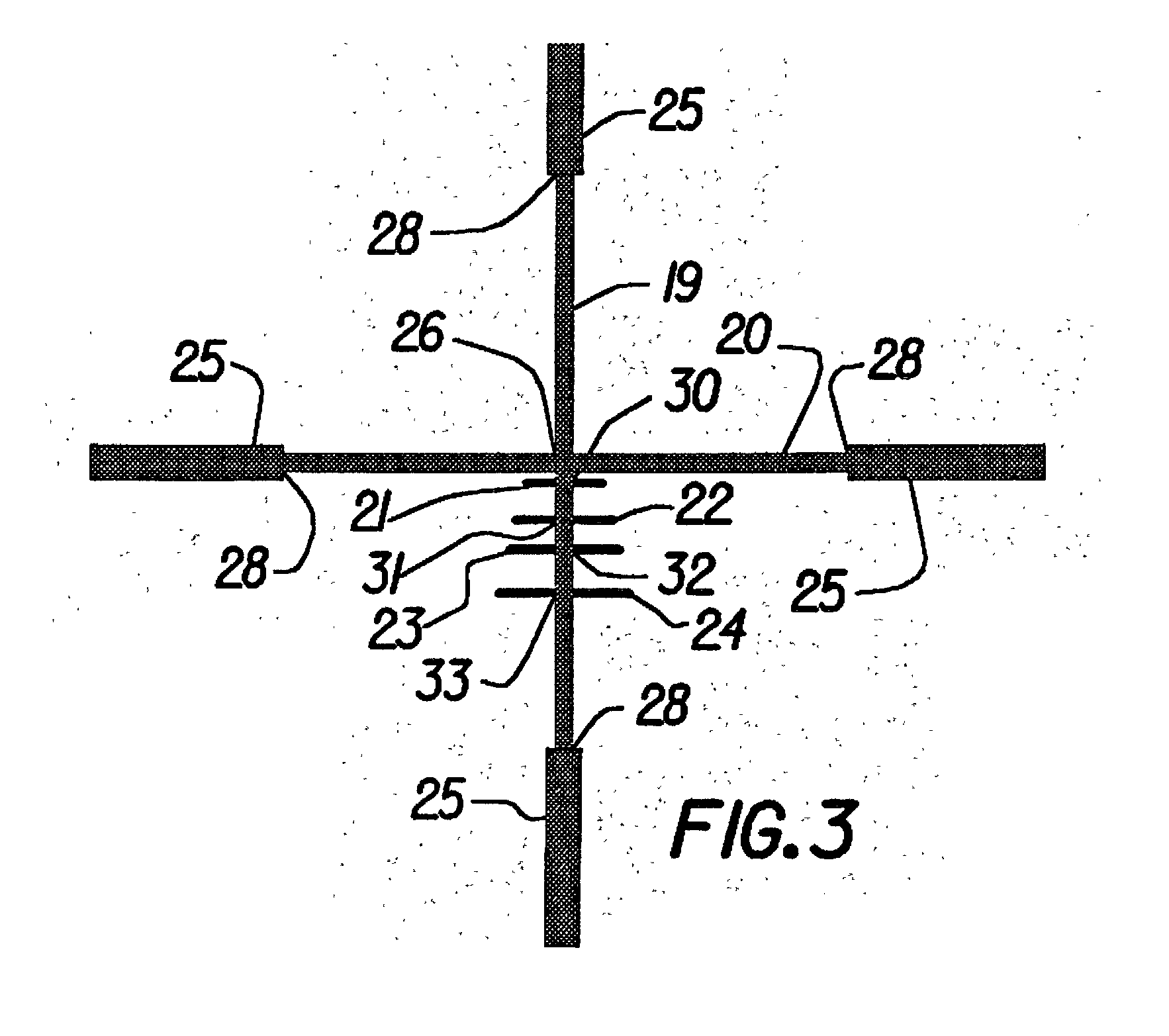
[0049] The reticle 16 is a circular, planar or ...


PUM


Abstract

A gunsight reticle defines a system of dimensioned indicia spaced at specific separations to improve aiming accuracy of a gun. The indicia may include perpendicularly intersecting center vertical and center horizontal hairlines, and four (or more or less) horizontal range-marker lines disposed at specific angular separations below the horizontal hairline in bisected relationship with the center vertical hairline. Spacing of the range marker lines below the center horizontal hairline is proportional to bullet drop at selected ranges, depending upon ballistic characteristics of bullet used. Relative lengths of said range-marker bars on each side of the central vertical crosshair are proportional to a specific crosswind (say 10 mph) at target range reflected by respective range marker. The method involves employing this reticle to determine distance to target, and using distance thus determined to ascertain a precise aiming point on the reticle. These indicia also have other useful characteristics that allow the shooter to easily mentally calculate corrections for crosswind, moving targets and shooting at targets that are above or below the shooter at a significant angle.

Description

BACKGROUND OF THE INVENTION [0001] 1. Field of Invention [0002] This invention relates to telescopic and other optical sighting systems for use on guns and other projectile delivering systems of all types but will herein it will be described as primarily applied to telescopic sights on typical rifles. More particularly, this invention relates most naturally to a telescopic gunsight equipped with a transparent aiming reticle and a method for using that reticle on a gun but it is certainly not constrained to that specific application. [0003] 2. Description of Prior Art [0004] It is well known that the line of sight between a shooter's eye and a target is a straight line, whether using “iron” sights or a telescopic sight, while the trajectory of the projectile is never a straight line (when passing though a gravitational field, the trajectory follows a ballistic parabola), which becomes of particular importance for projectile flights covering long distances. Accordingly, in order to ac...

Claims


Application Information

Patent Timeline
IPC IPC(8): F41G1/38G02B23/14G02B27/32
CPCF41G1/38G02B27/32G02B23/14F41G1/473
Inventor SMITH, THOMAS D.
Owner SMITH THOMAS D III
Why Eureka
Try Eureka