
Drag board assembly and method of applying a contact pad to a drag board

a technology of contact pads and drag boards, applied in the field of drag boards, can solve the problems of drag boards deteriorating, eventual destruction of boards, and existing contact pads of drag boards

Inactive Publication Date: 2004-04-29
LICHTENSTUL JOEL A
View PDF9 Cites 4 Cited by
  • Summary
  • Abstract
  • Description
  • Claims
  • Application Information

AI Technical Summary

Benefits of technology

[0012] Some of the advantages of the drag board apparatus and method of applying a contact pad to the present invention are positive, quick, and effective, installation of a contact pad on a drag board substrate, on-site replacement of a contact pad, ease of maintenance, no need of special tools for installing a contact pad, and no-need of a back-up drag board while a contact pad is being installed on a substrate. The present invention does not necessitate forming holes from the working surface of the substrate, reducing any deterioration effect of oils and such like on the substrate thereby increasing the useful life of the substrate.
[0013] The basic structure of the drag board apparatus of the present invention is simple in construction, relatively inexpensive to produce, and uncomplicated and efficient in its use. The apparatus is modifiable in various ways, for example, in 5 the material used for the substrate, the type of power drive for the locking system, and the type of material used for the contact pad.

Problems solved by technology

There are problems inherent in the existing drag board-contact pad arrangements.
Securing contact pads by nailing, stapling, or screwing results in deteriorating of the substrate.
The holes formed by the securing members allow oil which is part of the working environment to seep into the interior of the boards and eventual destruction of the boards.
Repeated use of the hook and loop arrangement in replacing contact pads results in deteriorating of the heads of the hooks rendering the system ineffective necessitating removal and replacement of the adhering layer.
It has also been known that the protective layers, such as lucite, of the hook and loop drag board arrangements have shattered in low temperature environments necessitating replacement.
Replacing the layers of the hook and loop drag board arrangements cannot be readily done at the coil processing site.
The drag boards are returned to a plant for time consuming and expensive refurbishing and re-laminating.
Certain of the hook and loop adhering layers cannot be refurbished or re-laminated and may only be discarded and replaced at significant expense.
Thus, the problems of the known and used drag board-contact pad arrangements are time-consuming expensive pad replacement, and substrate deterioration because of the holes formed in the substrate by the securing members.

Method used


Image

  • Drag board assembly and method of applying a contact pad to a drag board
  • Drag board assembly and method of applying a contact pad to a drag board
  • Drag board assembly and method of applying a contact pad to a drag board

Examples


Embodiment Construction

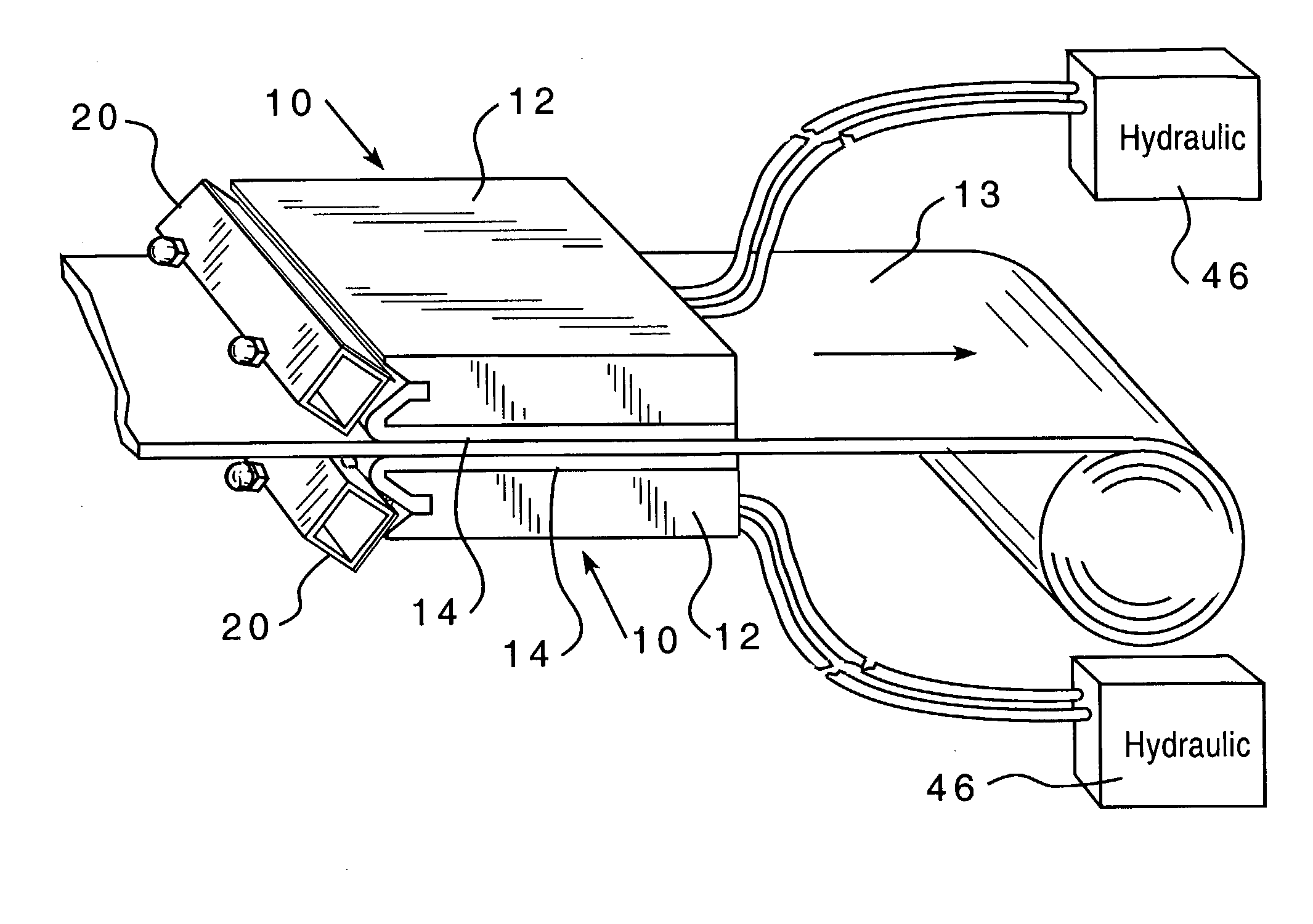
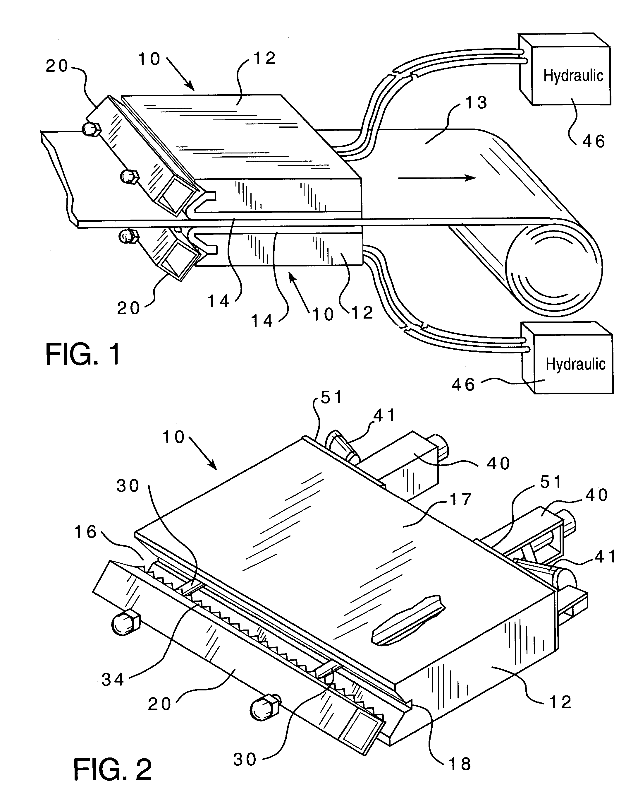
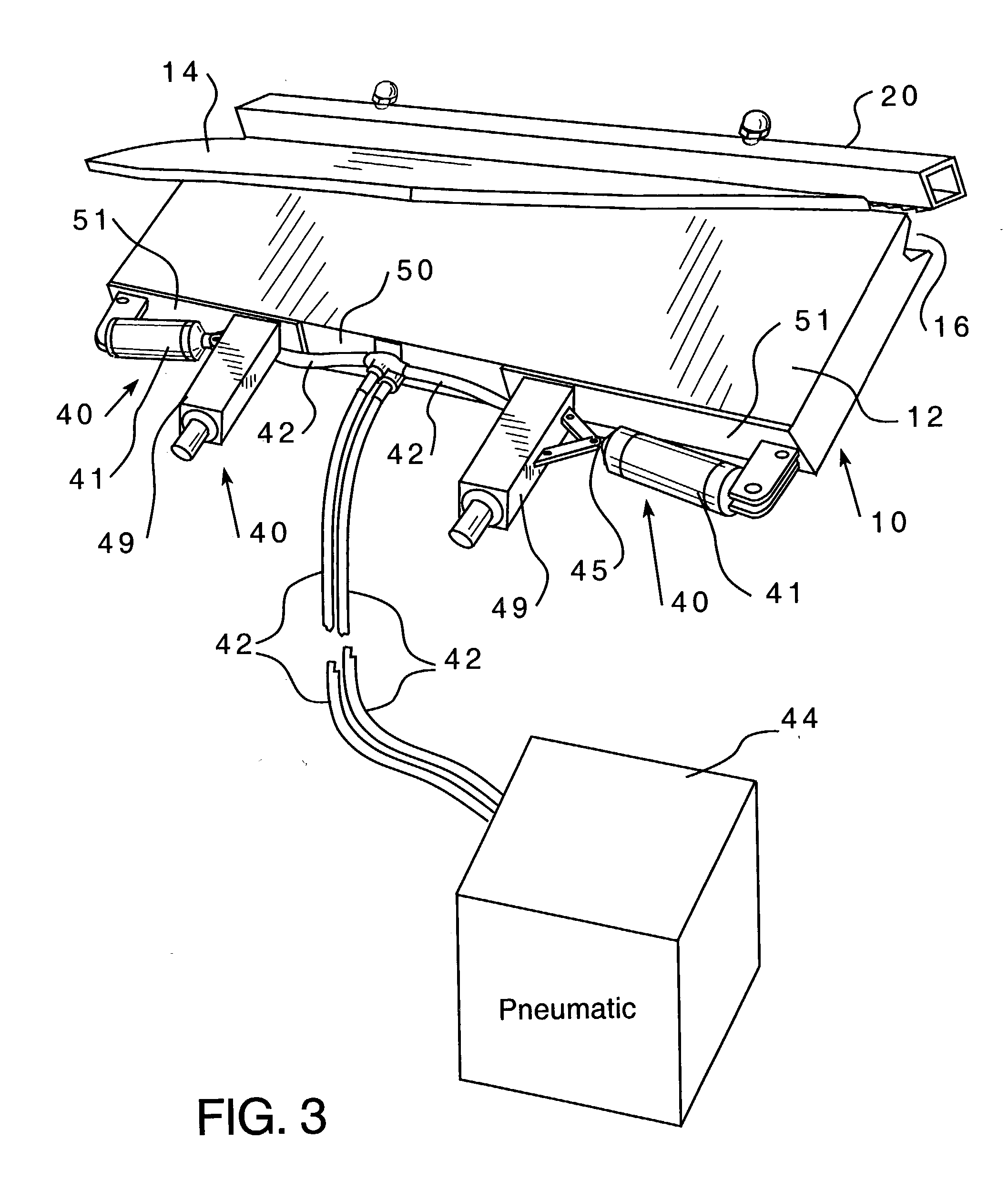
[0022] Referring now to the drawings there is shown a drag board assembly 10 embodying my present inventions, including an elongated substrate 12 formed in this embodiment of an ultrahigh molecular weight polyurethane which, as is well known in the art, is resistant to oil, acid and other chemicals. FIG. 1 shown a pair of drag board assemblies 10 in a somewhat diagrammatic representation arranged for wiping opposing surfaces of a continuous strip of material 13. Other applications include providing tension to portions of the strip on a processing line to facilitate handling. The drag board assembly 10 includes a contact pad 14 which is secured to the substrate 12 as will be described in specific detail hereinafter. FIG. 2 shows the drag board assembly 10 without an attached contact pad 14 for showing details of construction, the view looking to the leading edge section 16 of the substrate 12 which is the initial portion contacted by a moving strip on a processing line. The upper sur...


PUM

PropertyMeasurementUnit
Forceaaaaaaaaaa
Poweraaaaaaaaaa

Abstract

A drag board for use in a coil processing line for tensioning or wiping a continuous line of strip material using a substrate to which is selectively secured a contact pad. The leading edge section of the substrate is constructed and arranged for receiving a locking bar which may be activated to apply or release a compressive, securing force on one edge section of the contact pad. Releasing the locking bar permits removal of or emplacement of a contact pad from or onto the substrate.

Description

[0001] 1. Field of Invention[0002] This invention relates to a drag board for use in a coil processing line for tensioning or wiping a continuous line of strip material.[0003] 2. Description of the Prior Art[0004] Throughout various industries there are used continuous processes for handling coiled material, such as steel, paper, paper by-products, plastics, plastic by-products, aluminum, or other metal products. As part of these processes drag boards, known also as drag wipes, are used to produce tension in the strip to assist in recoiling it or to wipe or otherwise clean the surface of the metal strip.[0005] Most of the drag boards use a wooden substrate to which is attached a contact pad of felt, carpet, abrasive, or other media. The contact pad is secured to the substrate by nailing or stapling, or it may be held by a hook and loop attachment layer secured to the substrate. U.S. Pat. No. 5,722,577 discloses a drag board having a wooden substrate with a hook and loop layer arrang...

Claims


Application Information

Patent Timeline
IPC IPC(8): B21C47/00B65H23/10B65H77/00
CPCB21C47/003B65H2301/5115B65H23/10
Inventor LICHTENSTUL, JOEL A.
Owner LICHTENSTUL JOEL A
Learn More