Electrode catheter for intervention purposes

a technology of electrode catheter and electrode electrode, which is applied in the field of electrode electrode catheter for intervention purposes, can solve the problems of affecting the use of the device, and the inability of electrophysiological examination and intervention, such as ablation, and complicating production, so as to improve the usability of radiation fields and reduce the sensitivity. , the effect of good coupling of the supply lin

Active Publication Date: 2012-08-07
VASCOMED GMBH
View PDF19 Cites 4 Cited by
  • Summary
  • Abstract
  • Description
  • Claims
  • Application Information

AI Technical Summary

Benefits of technology

[0023]A design in which the long legs of the sections of the supply line provided by the direction change have a length which corresponds to approximately λ / 4 and in which the short legs have a length which corresponds to approximately λ / 8 has proven to be advantageous. If the legs are shorter than these values, the induced voltages cancel out increasingly less ideally, the damping effect of the configuration worsens, and the currents exiting at the ends of the electrode catheter become larger again than in the cited ideal construction.
[0025]The electrode catheter according to the present invention may finally be optimized in connection with the supply line insulation in regard to extensive insensitivity to high-frequency interfering fields and improving usability in radiation fields of magnetic resonance diagnostic devices by designing the insulation in such a way that it ensures good coupling of the supply line to the surrounding body tissue at the interfering frequency. For this purpose, the insulation may be very thin, which allows capacitive coupling, but is often precluded for reasons of mechanical ruggedness. Alternatively or additionally, the insulation of the supply line may also be produced from a minimally-insulating material or a material insulating as a function of frequency. This measure is the subject matter of application DE 10 2007 022 333.3 of the applicant. Briefly summarized, the quality of the resonant circuit formed by the electrode catheter with the body is reduced enough by this measure that on one hand the energy absorbed by the antenna is reduced and on the other hand the losses are distributed in the overall formation of electrode supply line / insulation / body in such a way that excess current concentration does not occur at specific points.

Problems solved by technology

Typical electrode catheters display the problem that electrode catheters of this type strongly heat the tissue in magnetic resonance diagnostic devices under the influence of the electromagnetic radiation generated thereby because of electromagnetic induction and the discharge of the induced energy in the area of their contact surface(s) to the tissue.
Because extremely strong heating of the tissue may occur in proximity to the electrode poles, the access to magnetic resonance diagnostic devices is typically blocked to wearers of cardiological and neurological intervention devices, such as cardiac pacemakers, neurostimulators, or defibrillators.
Electrophysiological examinations and interventions, such as ablations, are also not possible in MR devices.
The known solutions have the disadvantage that discrete components complicate the production and thus make it costly.
In addition, such discrete components reduce the reliability and long-term stability of electrode catheters, which is particularly disadvantageous if they are provided as long-term implants.
This is contrary to the attempts to design an implant as especially small and slim.

Method used


Image

  • Electrode catheter for intervention purposes
  • Electrode catheter for intervention purposes
  • Electrode catheter for intervention purposes

Examples


Embodiment Construction

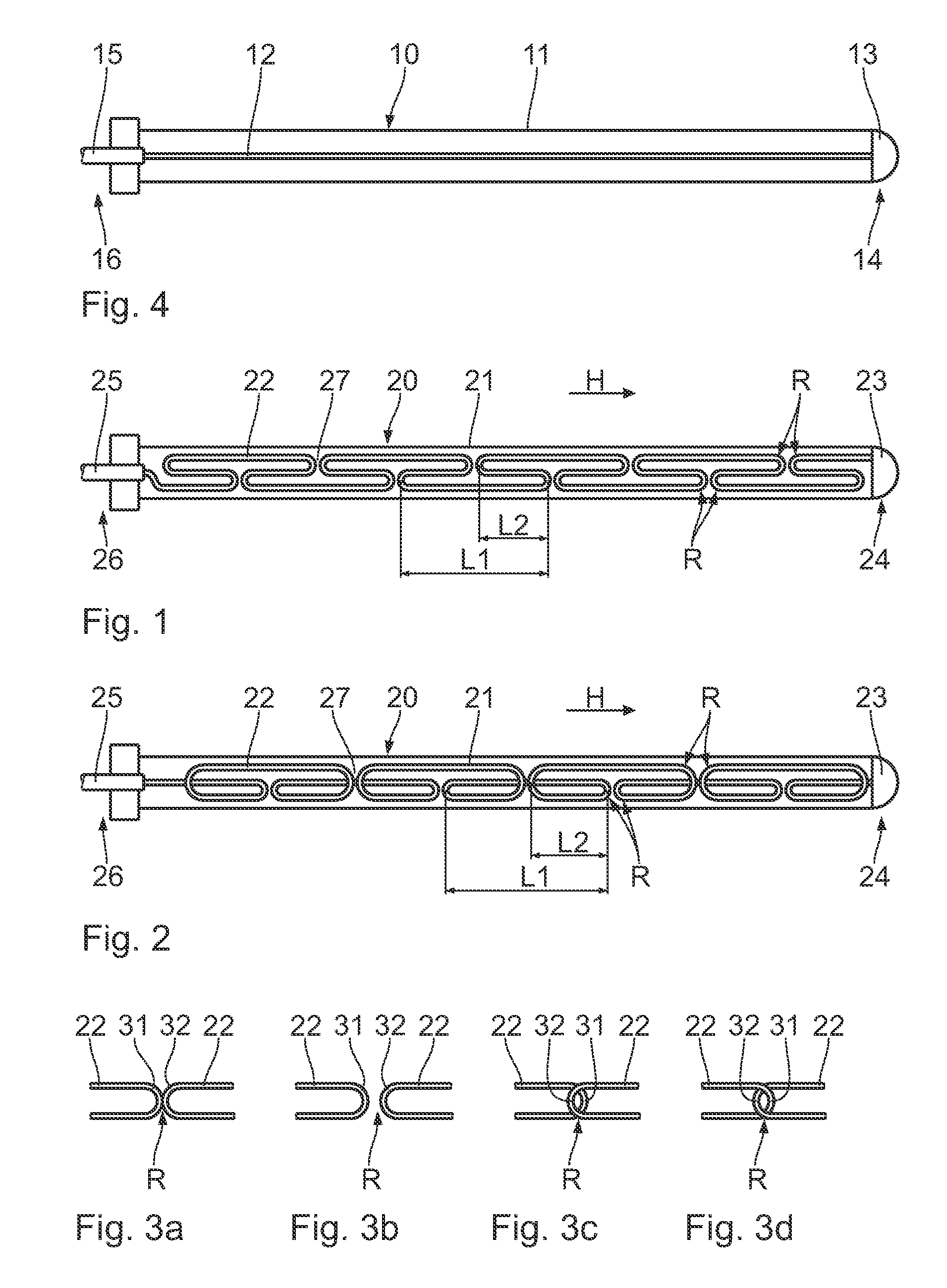
[0030]FIG. 4 schematically shows the prior art in the form a longitudinal section through an electrode catheter 10. The supply line 12 is essentially housed stretched in the shaft 11 of the electrode catheter 10. The supply line connects the electrode pole 13 at the distal end 14 of the electrode catheter to the connector 15, which produces the electrical connection to a device, at the proximal end 16 of the electrode catheter 10. Treatment devices such as implantable or external stimulators, cardiac pacemakers, or defibrillators are viewed as the device. However, diagnostic devices or combinations of treatment and diagnostic devices are also conceivable.

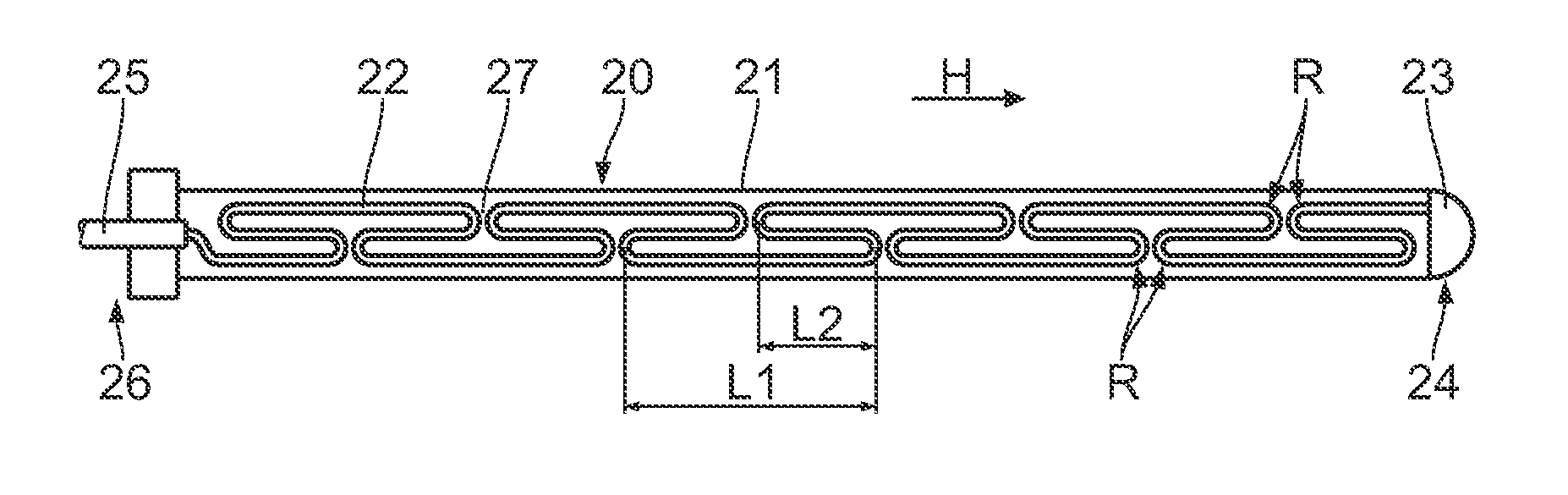
[0031]FIGS. 1 and 2 schematically show various embodiments of the configuration of a supply line 22 in the shaft 21 of an electrode catheter 20 according to the present invention. The supply line connects the electrode pole 23 at the distal end 24 of the electrode catheter to the connector 25 at the proximal end 26 of the electrode ...


PUM


Abstract

An electrode catheter that includes an elongate electrode catheter body having a distal end and a proximal end, at least one electrode pole in the area of the distal end of the electrode body, and at least one supply line, which runs insulated in the electrode body in the main direction (H) from the proximal end to the distal end, to the at least one electrode pole, wherein the at least one supply line is configured to desensitize the electrode catheter to the radiation of an electromagnetic field of an interfering frequency having a specific wavelength(λ), with the supply line changing its run direction at least twice in such a way that it runs at least once opposite to the main direction (H), the distance (L1,L2) between two direction changes (R) is shorter than half of the wavelength (λ / 2) of the interfering frequency.

Description

[0001]This application takes priority from German Patent Application DE 10 2006 054 620.2 filed 17 Nov. 2006, German Patent Application DE 10 2007 030 678.6 filed 2 Jul. 2007 and German Patent Application DE 10 2007 034 990.6 filed 26 Jul. 2007, the specifications of which are all hereby incorporated herein by reference.BACKGROUND OF THE INVENTION[0002]1. Field of the Invention[0003]The present invention relates to an electrode catheter for intervention purposes, such as a cardiac pacemaker, neurostimulator, ICD electrode, or EP catheter. The term “electrode catheter” is to be understood as all types of elongate implants which comprise at least one wire enclosed in the elongate body of the implant and running largely insulated from the patient therein using at least one surrounding medium, which is in direct or indirect electrical contact with the surrounding medium (e.g., body tissue) in proximity to the distal end. In addition to the above-mentioned types, for example, electrophys...

Claims


Application Information

Patent Timeline
Patent Type & Authority Patents(United States)
IPC IPC(8): A61B5/055A61N1/05
CPCA61N1/056A61N1/3718A61N2001/086A61N1/086
Inventor GEISTERT, WOLFGANG
Owner VASCOMED GMBH
Why Eureka
Try Eureka