Projecting zoom lens and projection display device

a projecting zoom and display device technology, applied in the field of projecting zoom lenses, can solve the problems of curvature of an image surface, increase in cost, and increase in lens size, and achieve the effects of wide angle of view, large zoom ratio, and long back focus

Inactive Publication Date: 2008-03-27
FUJI PHOTO OPTICAL CO LTD
View PDF5 Cites 6 Cited by
  • Summary
  • Abstract
  • Description
  • Claims
  • Application Information

AI Technical Summary

Benefits of technology

[0018]The invention has been made in light of the above circumstances, and provides a projecting zoom lens and a projection display device, which are capable of achieving a long back focus, a large zoom ratio, a wide ang

Problems solved by technology

In the case where a higher definition of the projecting zoom lens, a larger zoom ratio, and a wider angle obtained by increasing a diameter of an image circle on the reduction side are achieved in response to the demands 1 to 4, all measures to solve these problems lead to an increase in size of the lens and cause inevitably an increase in cost.
However, when it is attempted to reduce a size of the lens in which the reduction side is constructed as the telecentric system by any one of technologies disclosed in the above listed publications, a curvature of an S image surface occurs and it is difficult to attain a

Method used


Image

  • Projecting zoom lens and projection display device
  • Projecting zoom lens and projection display device
  • Projecting zoom lens and projection display device

Examples


example 1

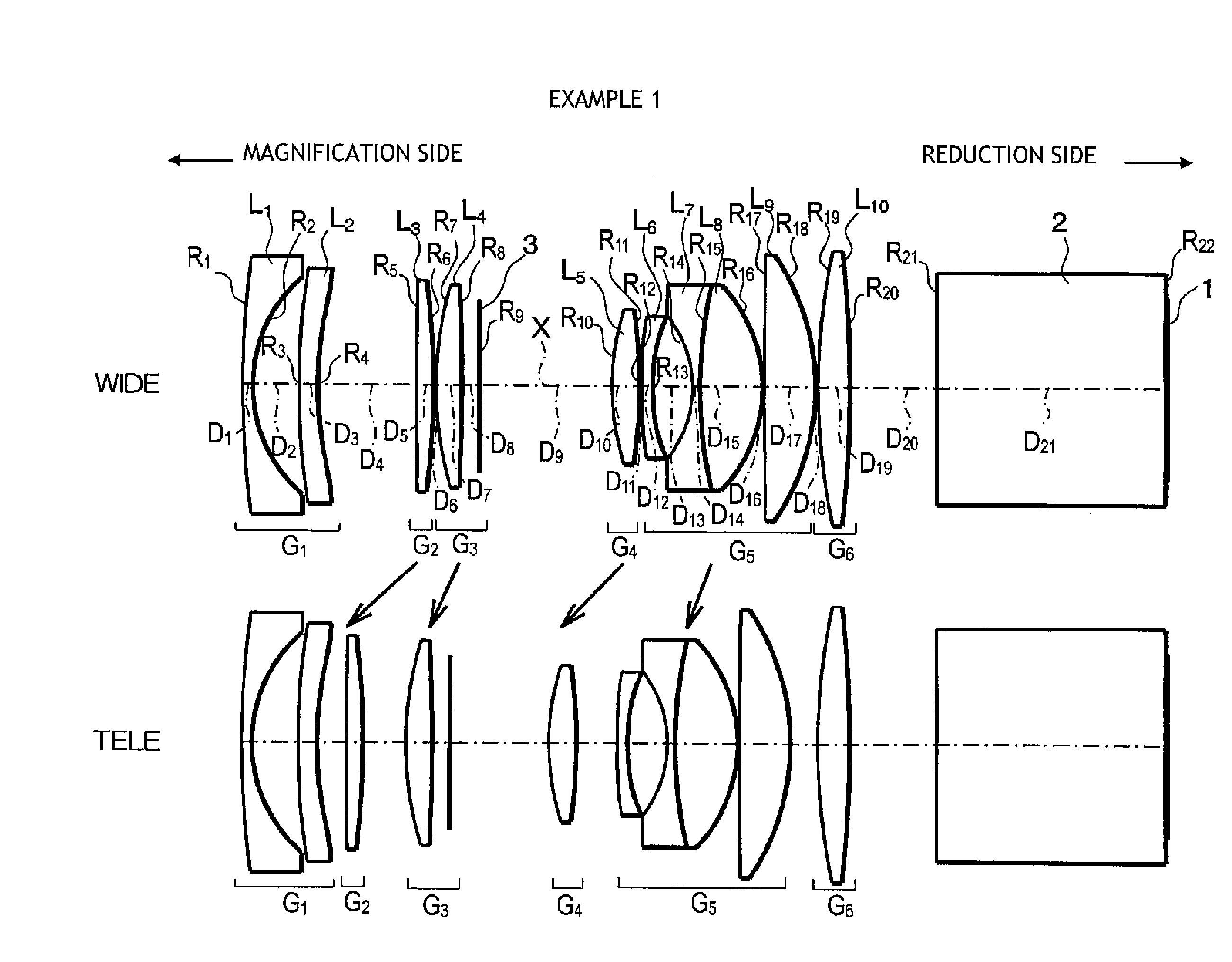
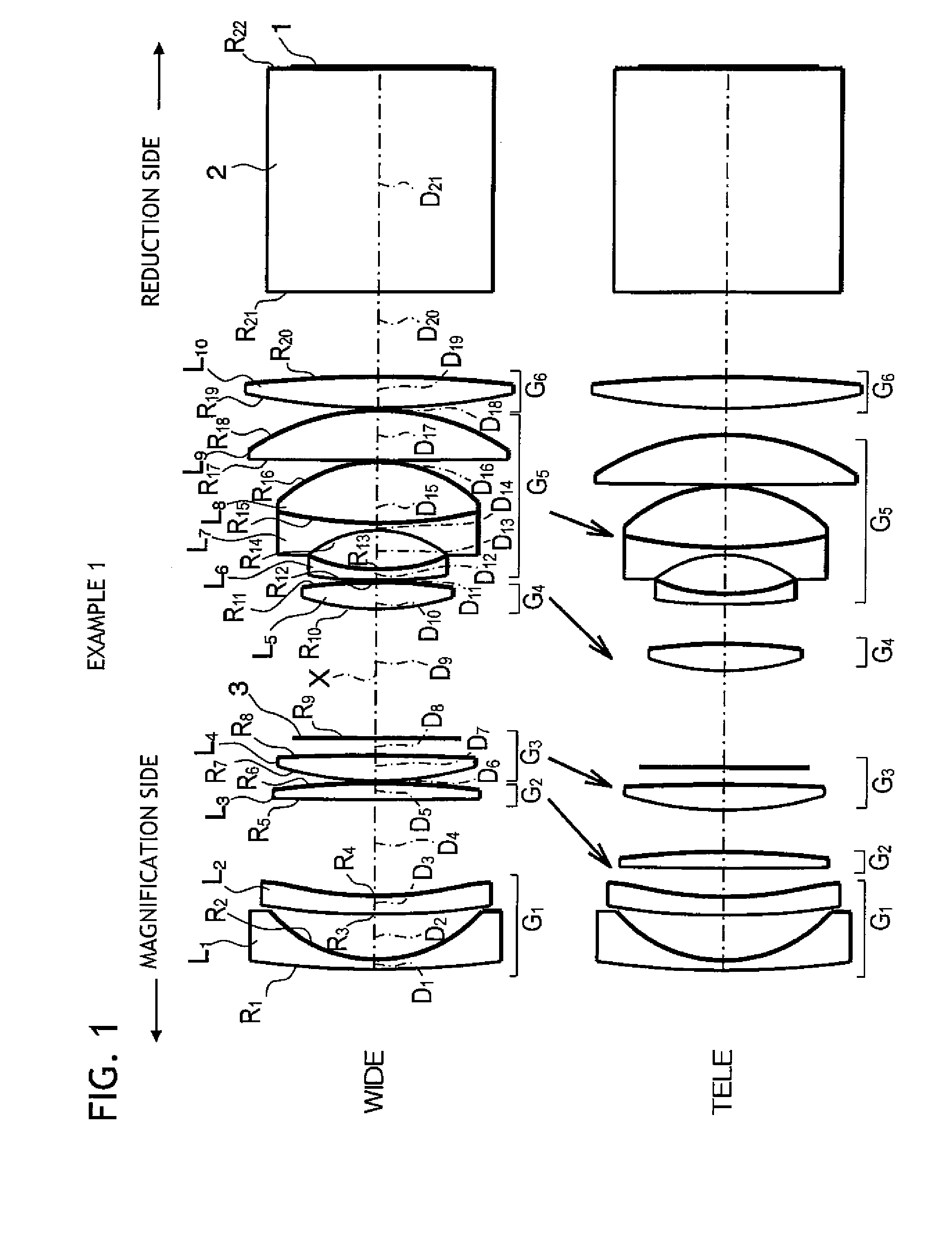
[0098]As described above, the projecting zoom lens according to Example 1 was constructed as shown in FIG. 1. That is, in this projecting zoom lens, the first lens group G1 included a first lens L1 formed of a negative meniscus lens having a convex surface directed to the magnification side, and a second lens L2 formed of a negative meniscus lens having a convex surface directed to the magnification side. Also, the second lens group G2 included a third lens L3 formed of a biconvex lens. The third lens group G3 included a fourth lens L4 formed of a biconvex lens. The fourth lens group G4 included a fifth lens L5 formed of a biconvex lens. Also, the fifth lens group G5 included a sixth lens L6 formed of a plano-concave lens having a flat surface, near the optical axis, directed to the magnification side, a cemented lens constructed by a seventh lens L7 formed of a biconcave lens and an eighth lens L8 formed of a biconvex lens, and a ninth lens L9 formed of a biconvex lens. Also, the s...

example 2

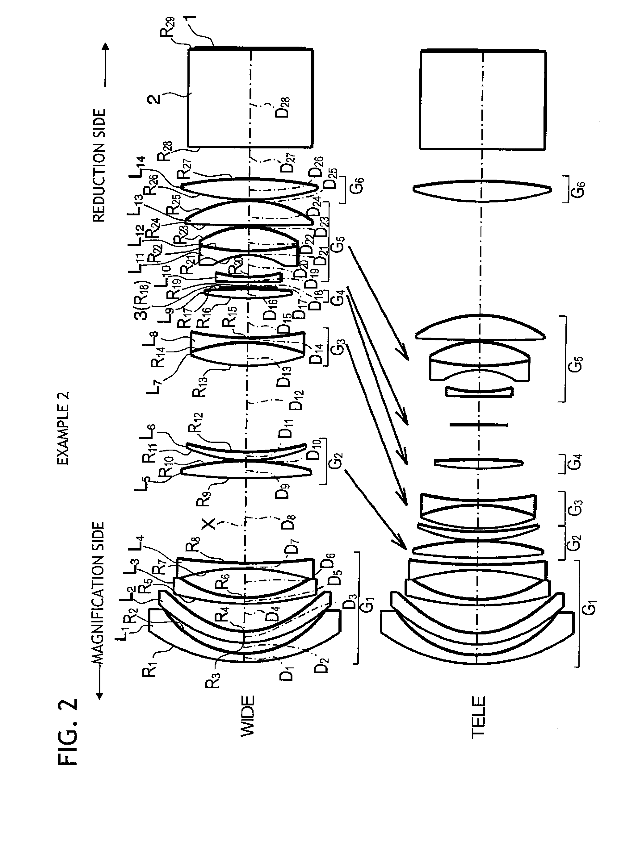
[0106]A schematic configuration of a projecting zoom lens according to Example 2 is shown in FIG. 2. The projecting zoom lens according to Example 2 was constructed substantially similarly to that in Example 1. In description for corresponding drawings, the like reference symbols are affixed to the like elements and thus redundant explanations will be omitted herein.

[0107]Example 2 is different from Example 1 mainly in lens configurations of the first lens group G1, the second lens group G2, and the third lens group G3 and in that the mask 3 is provided on the reduction side of the fourth lens group G4 and is moved independently of the respective lens groups.

[0108]In the configurations of the first lens group G1, the second lens group G2, and the third lens group G3 of the projecting zoom lens according to Example 2, the first lens group G1 included a first lens L1 formed of a negative meniscus lens having a convex surface directed to the magnification side, a second lens L2 formed ...

example 3

[0116]A schematic configuration of a projecting zoom lens according to Example 3 is shown in FIG. 3. The projecting zoom lens according to Example 3 was constructed substantially similarly to that in Example 1. In explanation of the corresponding drawings, the like reference symbols are affixed to the like elements and thus redundant explanations will be omitted herein.

[0117]Example 3 is different from Example 1 mainly in lens configurations of the first lens group G1, the third lens group G3, and the fifth lens group G5 are different and that the mask 3 is provided on the reduction side of the fourth lens L4 and is contained in the second lens group G2.

[0118]In the configurations of the first lens group G1, the third lens group G3, and the fifth lens group G5 of the projecting zoom lens according to Example 3, the first lens group G1 included a first lens L1 formed of a negative meniscus lens having a convex surface directed to the magnification side, a second lens L2 formed of a b...


PUM


Abstract

A power varying operation is performed by moving four lens groups out of six lens groups. A reduction side of a zoom lens is constructed as a substantially telecentric system. An aspheric lens is arranged in a pupil neighboring position where an effective aperture becomes smallest. Conditional Expressions (1) to (5) are satisfied.
1.2≦bf/fw   (1)
|fa/fw|≦4.5   (2)
φa/φim≦1.0   (3)
|ffaw/fw|≦1.5   (4)
E≦300×10−7 (/° C.)   (5)

Description

CROSS-REFERENCE TO RELATED APPLICATIONS[0001]This application is based upon and claims the benefit of priority from the Japanese Patent Application No. 2006-261209 filed on Sep. 26, 2006, the entire contents of which are incorporated herein by reference.BACKGROUND OF THE INVENTION[0002]1. Technical Field[0003]The invention relates to a projecting zoom lens installed into a projection display device and the projection display device and, more particularly, relates to a projecting zoom lens for use in a projector system into which a light valve such as a transmission type liquid crystal, a reflection type liquid crystal or DMD (Digital Micromirror Device) is installed and a projection display device.[0004]2. Description of the Related Art[0005]Nowadays the demand for a projection type projector is rising rapidly with the spread of personal computers.[0006]Known as a light valve used in such a projection type projector to optically modulate illumination light based on a video signal, a...

Claims


Application Information

Patent Timeline
IPC IPC(8): G02B15/14
CPCG02B15/177G02B15/1455G02B15/1465
Inventor YAMAMOTO, CHIKARA
Owner FUJI PHOTO OPTICAL CO LTD
Why Eureka
Try Eureka