Imaging lens and imaging apparatus

a technology of imaging apparatus and lens, applied in the field of imaging lens and imaging apparatus, can solve the problems of lateral chromatic aberration, and achieve the effect of long back focus

Inactive Publication Date: 2015-02-03
TIANJIN OFILM OPTO ELECTRONICS CO LTD
View PDF16 Cites 5 Cited by
  • Summary
  • Abstract
  • Description
  • Claims
  • Application Information

AI Technical Summary

Benefits of technology

[0031]According to the present invention, the refractive power, the shape and the like of each lens are appropriately set, and the system is structured in such a manner to include a cemented lens on either side of a stop. Further, predetermined formulas about the material of lenses constituting the cemented lens or lenses are satisfied. Therefore, it is possible to provide an imaging lens having both a long back focus and a wide angle of view, and in which chromatic aberrations are corrected in an excellent manner, and an imaging apparatus including the imaging lens.

Problems solved by technology

The lateral chromatic aberration tends to be a problem in widening an angle of view and in using a lens system in combination with an imaging device.

Method used


Image

  • Imaging lens and imaging apparatus
  • Imaging lens and imaging apparatus
  • Imaging lens and imaging apparatus

Examples


Embodiment Construction

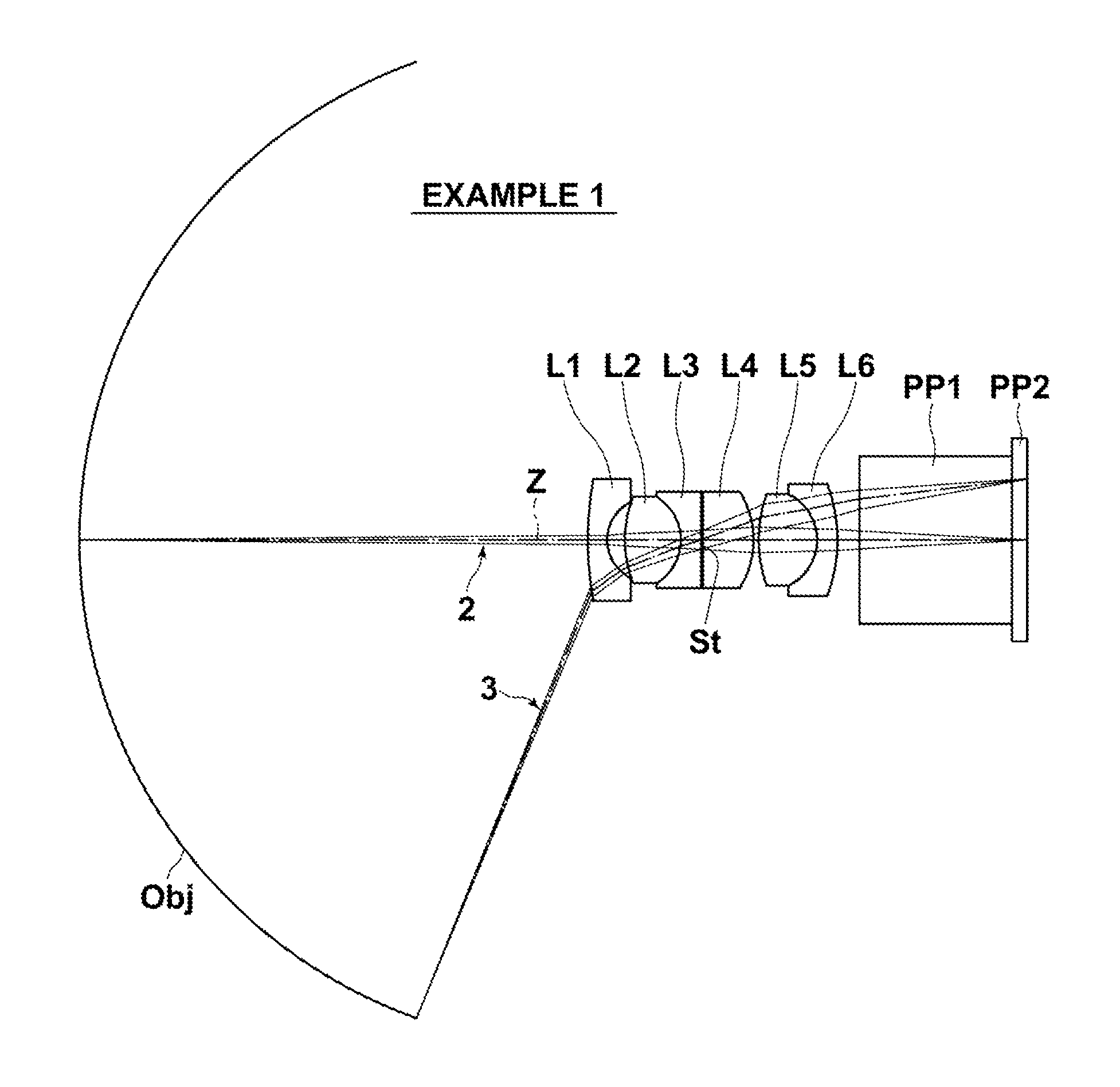
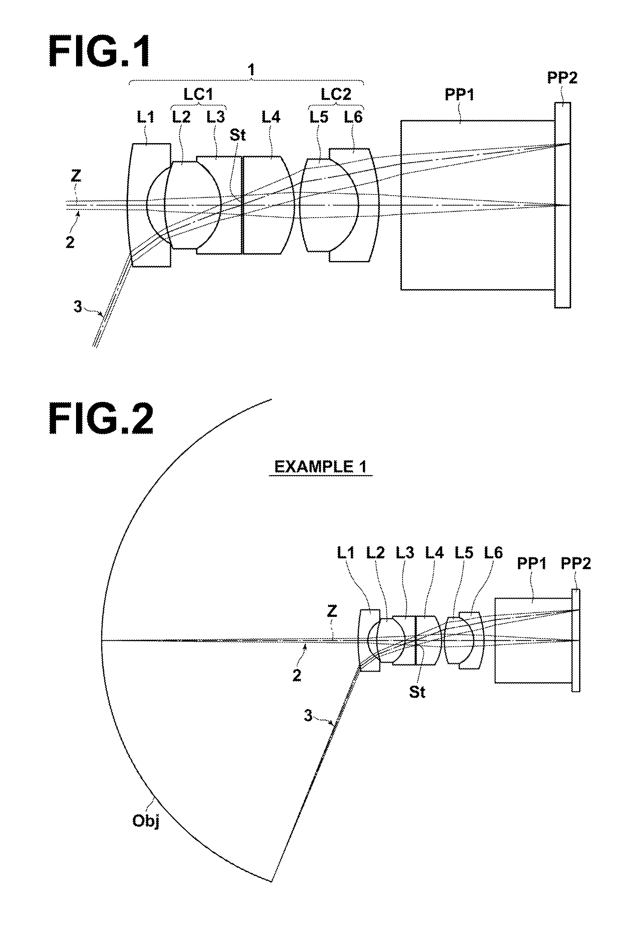
[0060]Hereinafter, with reference to drawings, an embodiment of the present invention will be described in detail. FIG. 1 illustrates the structure of an imaging lens 1 according to an embodiment of the present invention on a cross section including optical axis Z. The example of structure illustrated in FIG. 1 corresponds to a lens structure in Example 1, which will be described later. In FIG. 1, the left side is an object side, and a right side is an image side. In FIG. 1, axial rays 2 and off-axial rays 3 at a maximum angle of view are also illustrated. FIG. 1 illustrates an example in which parallel-flat-plate-shaped optical members PP1 and PP2, which are assumed to be an optical path conversion prism, a filter, a cover glass, or the like, are arranged on the image side of the imaging lens 1.

[0061]The imaging lens 1 has 4-group 6-lens structure, and consists of first lens L1, first cemented lens LC1 composed of second lens L2 and third lens L3 cemented together, fourth lens L4, ...


PUM


Abstract

An imaging lens has a negative first-lens, a first-cemented-lens of a second-lens and a third-lens, a stop, a positive fourth-lens, and a second-cemented-lens of a fifth-lens and a sixth-lens in this order from an object-side. The first-lens has a plano-concave or meniscus shape with a concave image-side surface. One of the second-lens and the third-lens is a positive lens and the other one is a negative lens. An object-side surface of the fourth-lens is a flat surface or a surface with a curvature radius having an absolute value greater than that of its image-side surface. One of the fifth-lens and the sixth-lens is a positive lens and the other one is a negative lens.

Description

CROSS REFERENCE TO RELATED APPLICATIONS[0001]This application is a continuation of PCT / JP2012 / 001822 filed on Mar. 15, 2012, which claims foreign priority to Japanese application No. 2011-060039 filed on Mar. 18, 2011. The entire contents of each of the above applications are hereby incorporated by reference.BACKGROUND OF THE INVENTION[0002]1. Field of the Invention[0003]The present invention relates to an imaging lens and an imaging apparatus. In particular, the present invention relates to an imaging lens having a wide angle of view and a long back focus, and an imaging apparatus including the imaging lens.[0004]2. Description of the Related Art[0005]Conventionally, small wide-angle imaging lenses were used in the fields of in-vehicle cameras, surveillance cameras, endoscopes and the like. In recent years, an imaging lens is generally used in combination with an imaging device that images an image formed by the imaging lens. In such a case, an optical low-pass filter, an infrared ...

Claims


Application Information

Patent Timeline
Patent Type & Authority Patents(United States)
IPC IPC(8): G02B9/34G02B13/18G02B13/04G02B13/06G02B23/24
CPCG02B13/04G02B9/34G02B13/06G02B23/243
Inventor MIYANO, HITOSHI
Owner TIANJIN OFILM OPTO ELECTRONICS CO LTD
Why Eureka
Try Eureka