Projection lens unit and rear projection type image display system

a projection lens and display system technology, applied in the field of projection lens units and projection type image display systems, can solve the problems of aberration correction and longer back focus of the projection lens

Inactive Publication Date: 2005-03-10
HITACHI LTD
View PDF12 Cites 4 Cited by
  • Summary
  • Abstract
  • Description
  • Claims
  • Application Information

AI Technical Summary

Benefits of technology

The present invention is devised in view of the above-mentioned problems inherent to the conventional rear projection type image display system,

Problems solved by technology

This means that the back focus of the projection lens becomes longer, and in ge

Method used


Image

  • Projection lens unit and rear projection type image display system
  • Projection lens unit and rear projection type image display system
  • Projection lens unit and rear projection type image display system

Examples


Embodiment Construction

Explanation will be hereinbelow made of several embodiments of the present invention with reference to the accompanying drawings in which like reference numerals are used to denote like parts.

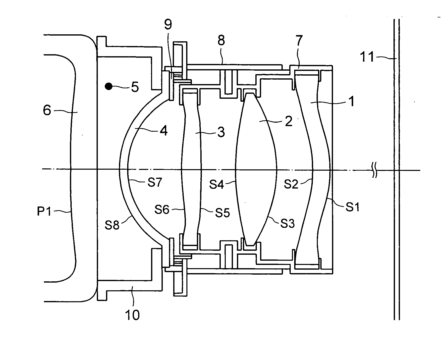
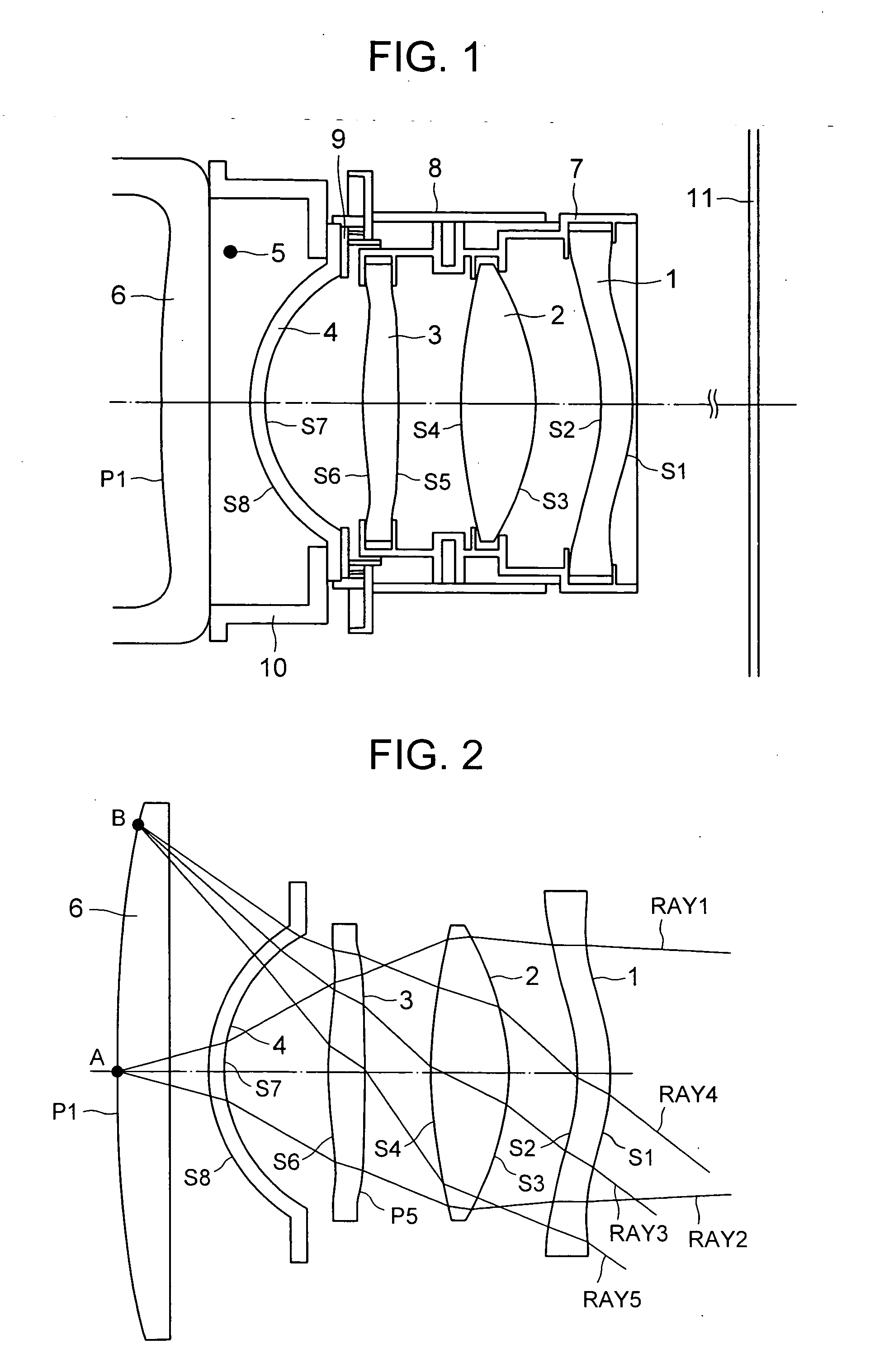
FIG. 1 is a sectional view illustrating a main portion of a projection lens unit in an embodiment of the present invention, having a sectional configuration on the basis of lens data exhibited in Table 1. Explanation will be hereinbelow made of workings of respective lenses in the embodiment of the present invention shown in FIG. 1, with reference both FIGS. 1 and 2. A first group lens 1 shown in FIG. 2 is a plastic lens for correcting spherical aberration for an imaging beam (having an upper hedge ray RAY1 and a lower hedge ray RAY2) traveling from an object point A on the optical axis, and correcting coma-aberration and astigmatism for an imaging beam (having an upper hedge ray RAY 4 and a lower hedge ray RAY 5) from an object point B on a peripheral part of a screen, A second group lens 2 ...


PUM


Abstract

An inexpensive projection lens unit in a rear projection type image display system, having a short focal distance (wide angle of viewing field), high focus and high contrast, and as well, including a power lens made of a glass material having a high refractive index in a range from 1.63 to 1.70 and an Abbe's number of not less than 50 with an optimized incident and emergent configuration in order to satisfactorily correct aberration with a enhanced focusing performance even with a shortened focal distance. Further, the power lens having a high refractive index can exhibit a high power, and accordingly, can carry out satisfactory aberration correction by optimizing the aspheric degree of a plastic lens even though the length of back focus is increased for enhancing the contrast.

Description

INCORPORATION BY REFERENCE The present application claims priority from Japanese application JP-2003-299475 filed on Aug. 25, 2003, the content of which is hereby incorporated by reference into this application. BACKGROUND OF THE INVENTION The present invention relates to a projection type image display system and a projection lens unit used therefor. A projection lens unit used in a rear projection type image display system have been known as disclosed in, for example, JP-A-1-250916 and JP-A-7-159688, JP-A-9-159914. JP-A-1-250916 discloses a four-group-four lens configuration consisting of a spherical glass lens having high dispersion and a low refractive index as a power lens having a highest positive refractive power, and three aspherical lenses, and JP-A-7-159688 discloses a five-group-five lens configuration consisting of a spherical glass lens having lowe dispersion and a high refractive index as the power lens, and four aspherical lenses while JP-A-9-159914 discloses a six...

Claims


Application Information

Patent Timeline
IPC IPC(8): G02B13/02G02B13/16G02B13/18G03B21/14
CPCG02B13/02
Inventor IKEDA, HIDEHIROKATO, SHUJIHIRATA, KOJIOGURA, NAOYUKI
Owner HITACHI LTD
Why Eureka
Try Eureka