Endoscopic objective optical system and imaging apparatus

a technology of objective optical system and imaging apparatus, which is applied in the field of endoscopic objective optical system, can solve problems such as the tendency of depth of field to become shallow

Active Publication Date: 2016-10-04
OLYMPUS CORP
View PDF22 Cites 5 Cited by
  • Summary
  • Abstract
  • Description
  • Claims
  • Application Information

AI Technical Summary

Benefits of technology

[0012]The present invention has been made in view of the above circumstances, and has an object to provide an endoscopic objective optical system which has a long back focus, allows placement of optical members such as a polarizing prism, makes aberrations less subject to manufacturing errors, and reduces variations in aberrations during focusing.Solution to Problem
[0016]By satisfying the above conditional expressions, the present aspect reduces variations in aberrations due to manufacturing errors and variations in aberrations due to focusing by prescribing the focal length of the focusing lens while allowing placement of optical members such as a polarizing prism. Specifically, the present aspect makes it possible to suppress aberrations due to manufacturing errors, decrease influence on deterioration of optical performance, and, for example, reduce side blur. Also, the present aspect makes it possible to suppress variations in aberrations due to focusing, decrease variations in astigmatic aberrations, and prevent an image surface from becoming liable to incline to a negative side on a side of shorter working distance. Note that the focusing lens has positive or negative weak refractive power.
[0017]Also, the present aspect makes it possible to decrease influence of eccentricity errors on deterioration of optical performance while maintaining sufficient refractive power of the front group so as to be advantageous for a wider angle of view and reducing high order off-axis aberrations.
[0018]Furthermore, the present aspect makes it possible to keep lens size in a desired range while maintaining refractive power of the rear group and ensuring back focus.
[0019]In the aspect described above, preferably the focusing lens has a positive refractive index; and focus is set to a side of shorter working distance by moving the focusing lens to an image side when the working distance changes from a longer side to the shorter side.
[0020]This makes it possible to set focus to the side of shorter working distance by moving the focusing lens to the image side on the optical axis.

Problems solved by technology

Also, in recent years, there has been a tendency for depth of field to become shallower due to increases in image quality of imaging devices.

Method used


Image

  • Endoscopic objective optical system and imaging apparatus
  • Endoscopic objective optical system and imaging apparatus
  • Endoscopic objective optical system and imaging apparatus

Examples


first embodiment

[0056]An objective optical system according to a first embodiment of the present invention will be described below with reference to the drawings.

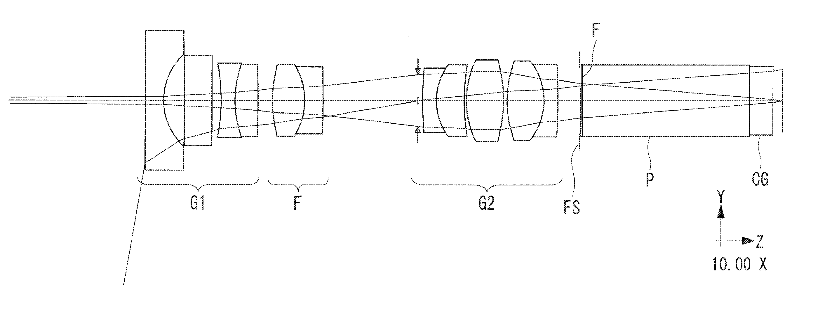
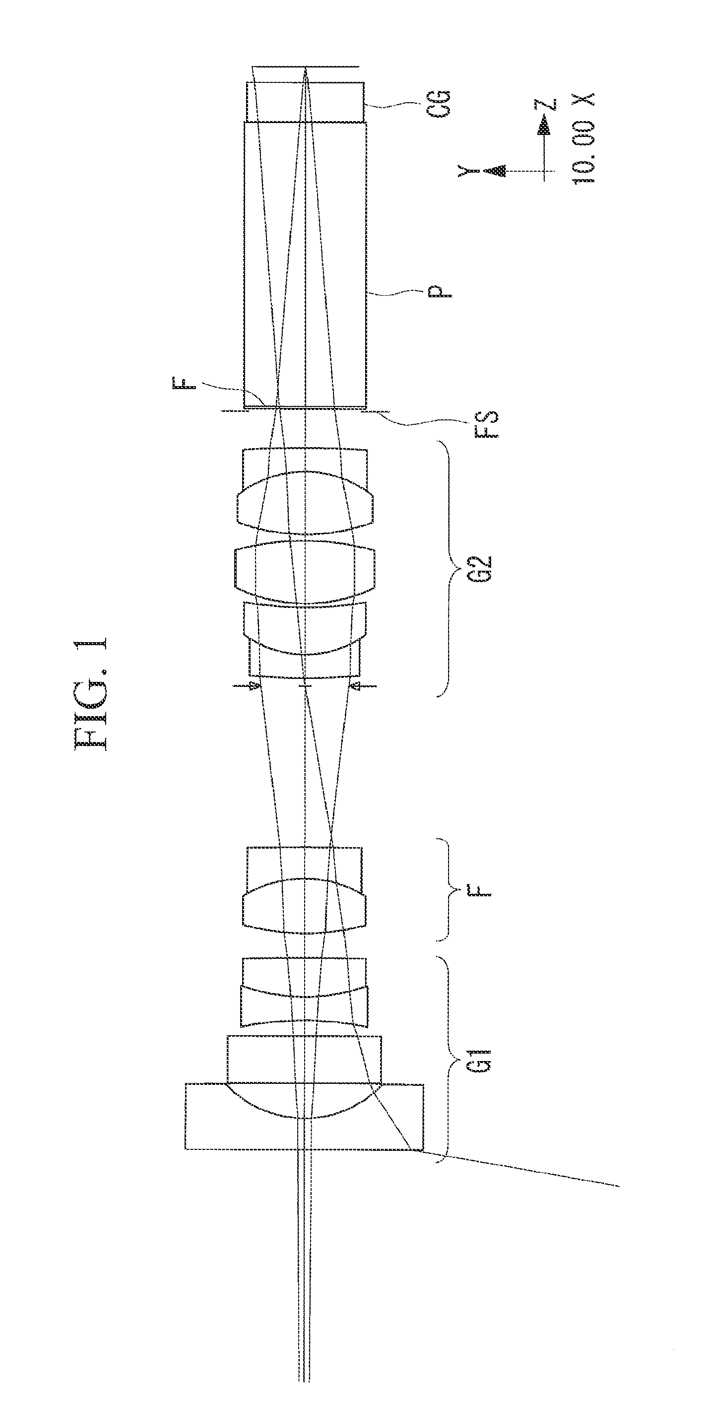
[0057]FIG. 1 is a sectional view showing an overall configuration of the endoscopic objective optical system 1 according to the present embodiment. As shown in FIG. 1, the endoscopic objective optical system 1 includes, in order from an object side, a front group G1 provided with negative refractive power (hereinafter referred to simply as “negative”), a focusing lens F, and a rear group G2 provided with positive refractive power (hereinafter referred to simply as “positive”).

[0058]An optical filter F, an optical prism P, and an optical member CG such as cover glass are placed on an image side of the positive rear group G2, where the cover glass is adapted to seal an imaging device (not shown).

[0059]The imaging device is placed near an image surface of the endoscopic objective optical system, making up the endoscopic objective optical syst...

example 1

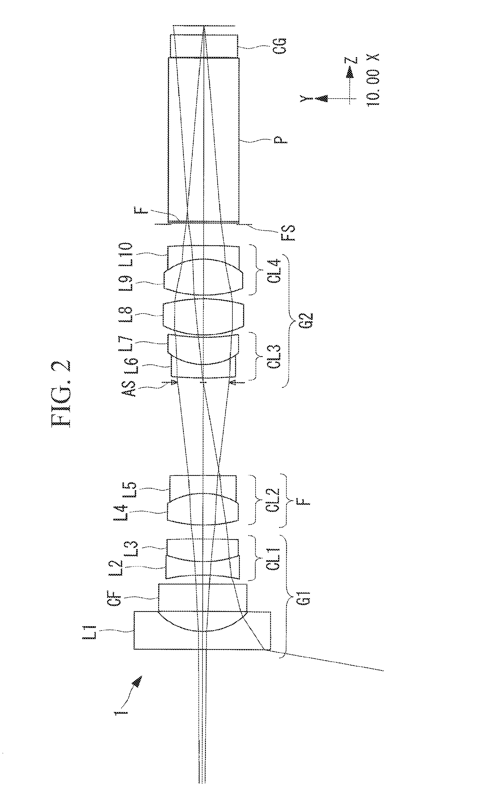
[0073]A configuration of an endoscopic objective optical system according to Example 1 of the present invention is shown in FIGS. 2 and 3. FIG. 3(a) shows a normal observation mode and FIG. 3(b) shows a short distance observation mode, and rays shown here include on-axis marginal rays and principal rays with a maximum angle of view. Also, an aberration curve in the normal observation mode of the endoscopic objective optical system according to the present example is shown in FIG. 4 and an aberration curve in the short distance observation mode is shown in FIG. 5.

[0074]As shown in FIG. 2, in the endoscopic objective optical system 1 according to Example 1, the negative front group G1 includes, in order from the object side, a first lens L1 which is a plano-concave lens with a planar surface on the object side, an infrared cut filter CF, a second lens L2 which is a double-concave lens, and a third lens L3 which is a double-convex lens. Of those lenses, the second lens L2 and third len...

example 2

[0081]A configuration of an endoscopic objective optical system according to Example 2 of the present invention is shown in FIGS. 6 and 7. FIG. 7(a) shows a normal observation mode and FIG. 7(b) shows a short distance observation mode, and rays shown here include on-axis marginal rays and principal rays with a maximum angle of view. Also, an aberration curve in the normal observation mode of the endoscopic objective optical system according to the present example is shown in FIG. 8 and an aberration curve in the short distance observation mode is shown in FIG. 9.

[0082]As shown in FIG. 6, in the endoscopic objective optical system 2 according to Example 2, the negative front group G1 includes, in order from the object side, a first lens L1 which is a plano-concave lens with a planar surface on the object side, an infrared cut filter CF, a second lens L2 which is a double-concave lens, and a third lens L3 which is a double-convex lens. Of those lenses, the second lens L2 and third len...


PUM


Abstract

To allow placement of optical members by providing a long back focus, make aberrations less subject to manufacturing errors, and reduce variations in aberrations during focusing. An endoscopic objective optical system includes, in order from an object side, a front group with negative refractive power, a focusing lens, and a rear group with positive refractive power, wherein: the endoscopic objective optical system satisfies conditional expressions (1) to (4) below:4<FB / FL  (1)FL / |fc|<0.1  (2)−3<F_F / FL<−0.9  (3)2.5<F_R / FL<5  (4)where FB is back focus of the entire system, FL is a focal length of the entire system, fc is a focal length of the focusing lens, |fc| is an absolute value of fc, F_F is a focal length of the front group, and F_R is a focal length of the rear group.

Description

CROSS-REFERENCE TO RELATED APPLICATIONS[0001]This application is a Continuation Application of International Application PCT / JP2013 / 085015 filed on Dec. 16, 2013, which claims priority to Japanese Application No. 2013-033440 filed on Feb. 22, 2013.The Contents of International Application PCT / JP2013 / 085015 and Japanese application No. 2013-033440 are hereby incorporated by reference herein in its entirety.TECHNICAL FIELD[0002]The present invention relates to an endoscopic objective optical system, and more particularly, to an endoscopic objective optical system with a long back focus.BACKGROUND ART[0003]In an endoscopic objective optical system, it is sometimes necessary to provide a long back focus in order to place optical members such as a prism in an optical path. Objective optical lenses provided with such a long back focus are proposed, for example, in Patent Literatures 1 and 2.[0004]According to both Patent Literatures 1 and 2, an optical member is placed between an objectiv...

Claims


Application Information

Patent Timeline
Patent Type & Authority Patents(United States)
IPC IPC(8): G02B23/24A61B1/00G02B27/10G02B13/04
CPCG02B23/243A61B1/00096A61B1/00188G02B13/04G02B23/2446G02B27/1066
Inventor UZAWA, TSUTOMUKATAKURA, MASAHIRO
Owner OLYMPUS CORP
Why Eureka
Try Eureka