
Valve that is normally closed in the free state

Active Publication Date: 2008-03-27
ALCON INC
View PDF19 Cites 17 Cited by
  • Summary
  • Abstract
  • Description
  • Claims
  • Application Information

AI Technical Summary

Benefits of technology

[0010] Embodiments of the present invention provide an advantage by eliminating unwanted fluid ingress into a cassette's aspiration path during cassette installation, during cassette setup, during the procedure, and upon cassette removal.
[0011] Embodiments of the present invention provide another advantage by preventing dribbling from the cassette aspiration ports after removal, thereby improving the overall cleanliness of a surgical procedure.
[0012] Embodiments of the present invention provide another advantage by providing active control to fail safe during a power loss condition.

Problems solved by technology

The human eye can suffer a number of maladies causing mild deterioration to complete loss of vision.
However, current cassette designs utilize valves that are classified as “normally open,” meaning that the valves are open unless they are actively engaged in order to close them.
Further, normally open valves can result in the dribbling of liquids from the cassette ports when removed from the receiver, which limits the overall cleanliness of a surgical procedure.
Further still, for some applications, normally open valves do not “fail safe” in a loss of power situation, resulting in potentially unwanted fluid flow when power is lost.

Method used


Image

  • Valve that is normally closed in the free state
  • Valve that is normally closed in the free state
  • Valve that is normally closed in the free state

Examples


Embodiment Construction

[0019] Preferred embodiments of the invention are illustrated in the FIGURES, like numerals being used to refer to like and corresponding parts of the various drawings.

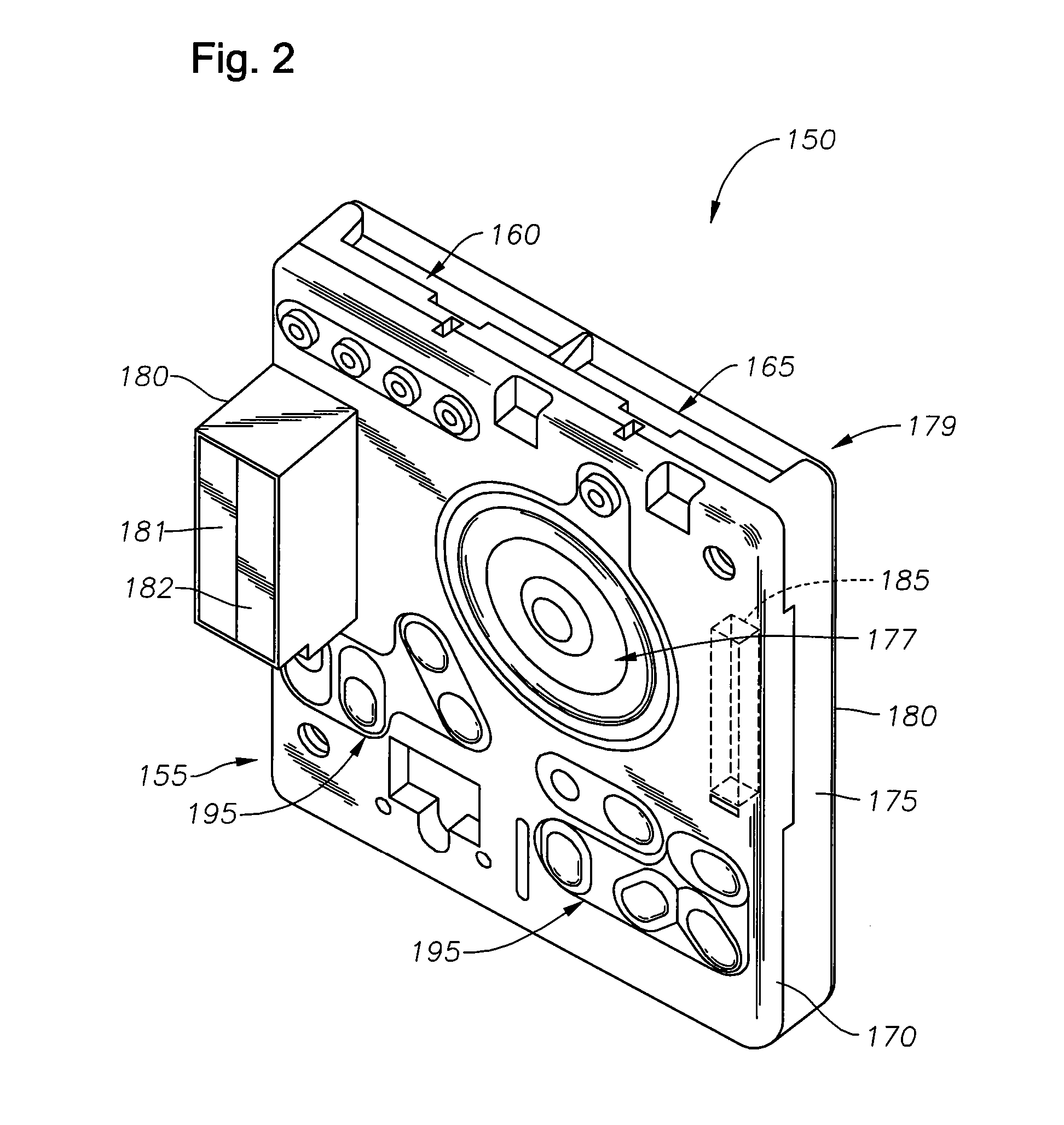
[0020] Embodiments of the present invention include a valve that is normally closed, meaning under static steady-state conditions no fluid can pass through the valve. According to one embodiment, the valve seal face can be the rim on an underside of an elastomeric hollow mushroom or conical shaped valve boss and the valve seat can be the rim of a through-hole designed such that no fluid can pass through the valve unless a force is applied to the inner surface of the valve boss. According to a preferred embodiment, the valve would be employed in a fluidics cassette adapted for use in an ophthalmic surgical console.

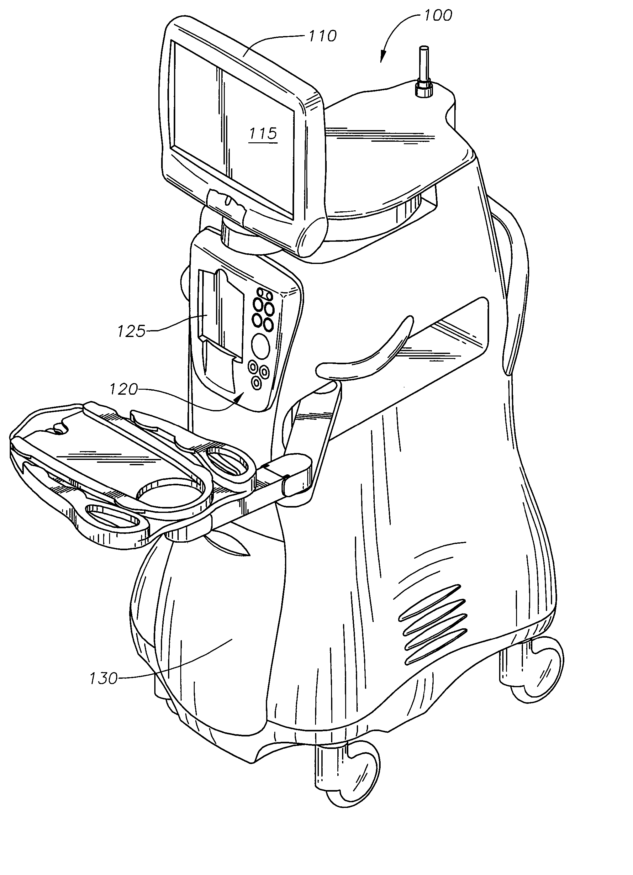
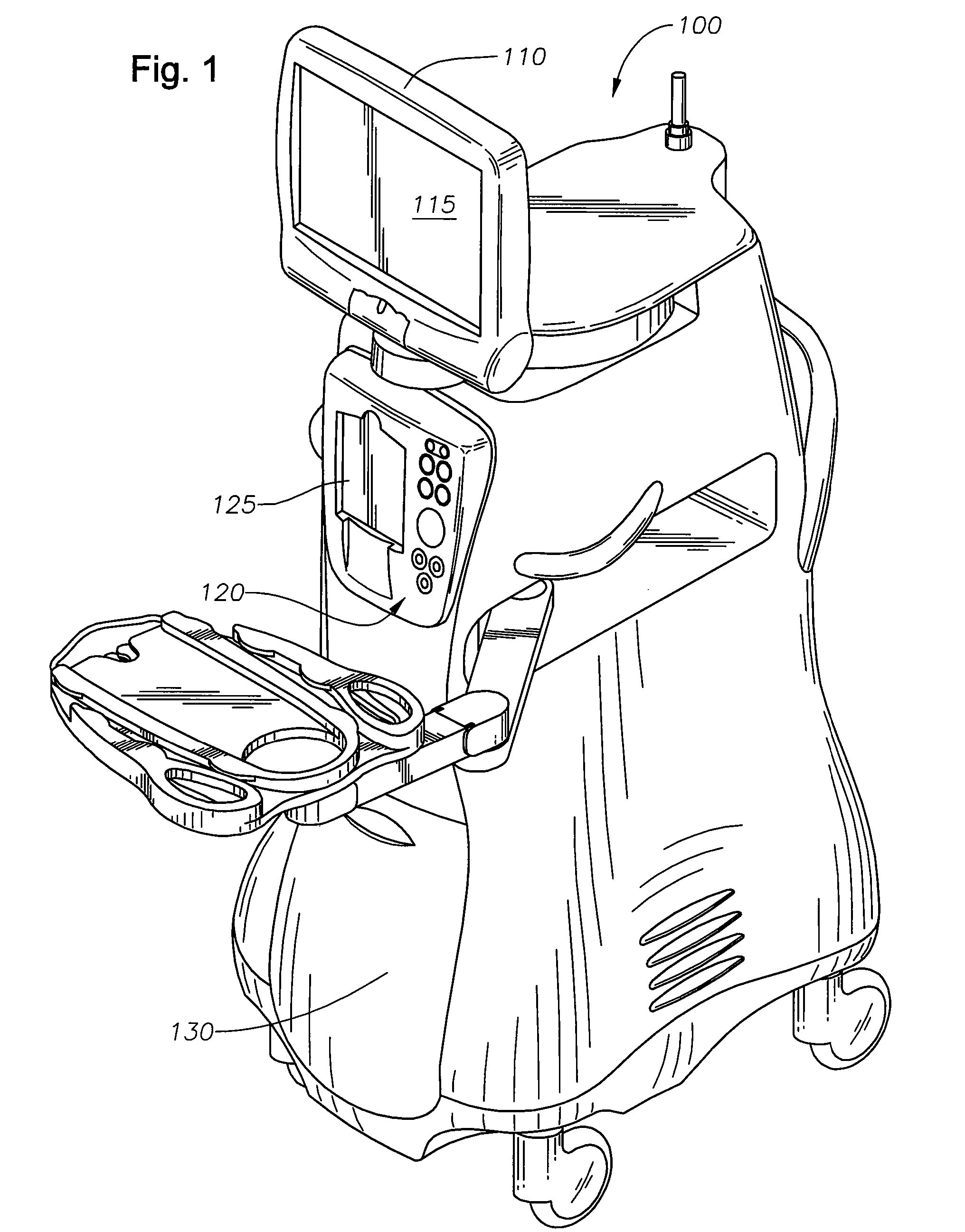
[0021]FIG. 1 is a diagrammatic representation of one embodiment of an ophthalmic surgical console 100. Surgical console 100 can include a swivel monitor 110 that has touch screen 115. Swivel monitor 110 can...


PUM


Abstract

A valve system comprising a valve design in which the valve is normally closed is disclosed. The normally closed valve can comprise a circular valve seal face formed by the underside of a rim of an elastomeric valve boss and a circular valve seat, which is formed by the rim of a through-hole molded into, for example, a plastic cassette, such that the valve seal face, the valve seat, and the through hole are concentric. The valve boss can be a hollow “mushroom” shaped valve boss, or a conical-shaped valve boss. If no force is applied to the inside surface of the valve boss, no fluid can pass through the valve as the valve seal face rests against the valve seat as a result of the steady free-state load created by the stretch of the valve boss over the slightly longer through hole. When a force is applied to the inside surface of the valve boss, the valve seal face is displaced from the valve seat, allowing fluid between the valve seal face and valve seat and then to pass between the valve boss and the inside surface of the through hole.

Description

CROSS-REFERENCE TO RELATED APPLICATIONS [0001] This application claims priority under 35 U.S.C. §119 to U.S. Provisional Patent Application No. 60 / 847,159, filed Sep. 26, 2006, the entire contents of which are incorporated herein by reference.TECHNICAL FIELD OF THE INVENTION [0002] The present invention relates to surgical systems and methods. More particularly, the present invention relates to valve design employed in surgical cassettes used in an ophthalmic surgical system. BACKGROUND OF THE INVENTION [0003] The human eye can suffer a number of maladies causing mild deterioration to complete loss of vision. While contact lenses and eyeglasses can compensate for some ailments, ophthalmic surgery is required for others. Generally, ophthalmic surgery is classified into posterior segment procedures, such as vitreoretinal surgery, and anterior segment procedures, such as cataract surgery. More recently, combined anterior and posterior segment procedures have been developed. [0004] The ...

Claims


Application Information

Patent Timeline
IPC IPC(8): A61M35/00
CPCF16K1/12A61F9/007A61F9/00
Inventor WILLIAMS, DAVID LLOYD
Owner ALCON INC
Learn More