Selective detailed display of devices in a network

Active Publication Date: 2008-03-27
SIEMENS AG
View PDF11 Cites 56 Cited by
  • Summary
  • Abstract
  • Description
  • Claims
  • Application Information

AI Technical Summary

Benefits of technology

[0015]In a further advantageous embodiment at least one temporary view of the respective device is displayed in a transition phase when the detailed view is activated or deactivated for at least one selected device. The impression of an animated transition can also be generated with a plurality of temporary views. This change in the appearance of the device in a transition phase that may be experienced over time by the user means that the transition from the overview to the detailed

Problems solved by technology

High information densities are difficult for an operator or user to capture, i.e. there is a need to keep them low (central usability approach).
The problem here is that in the case of devices with a plurality of network interfaces the situation can occur where

Method used


Image

  • Selective detailed display of devices in a network
  • Selective detailed display of devices in a network

Examples


Embodiment Construction

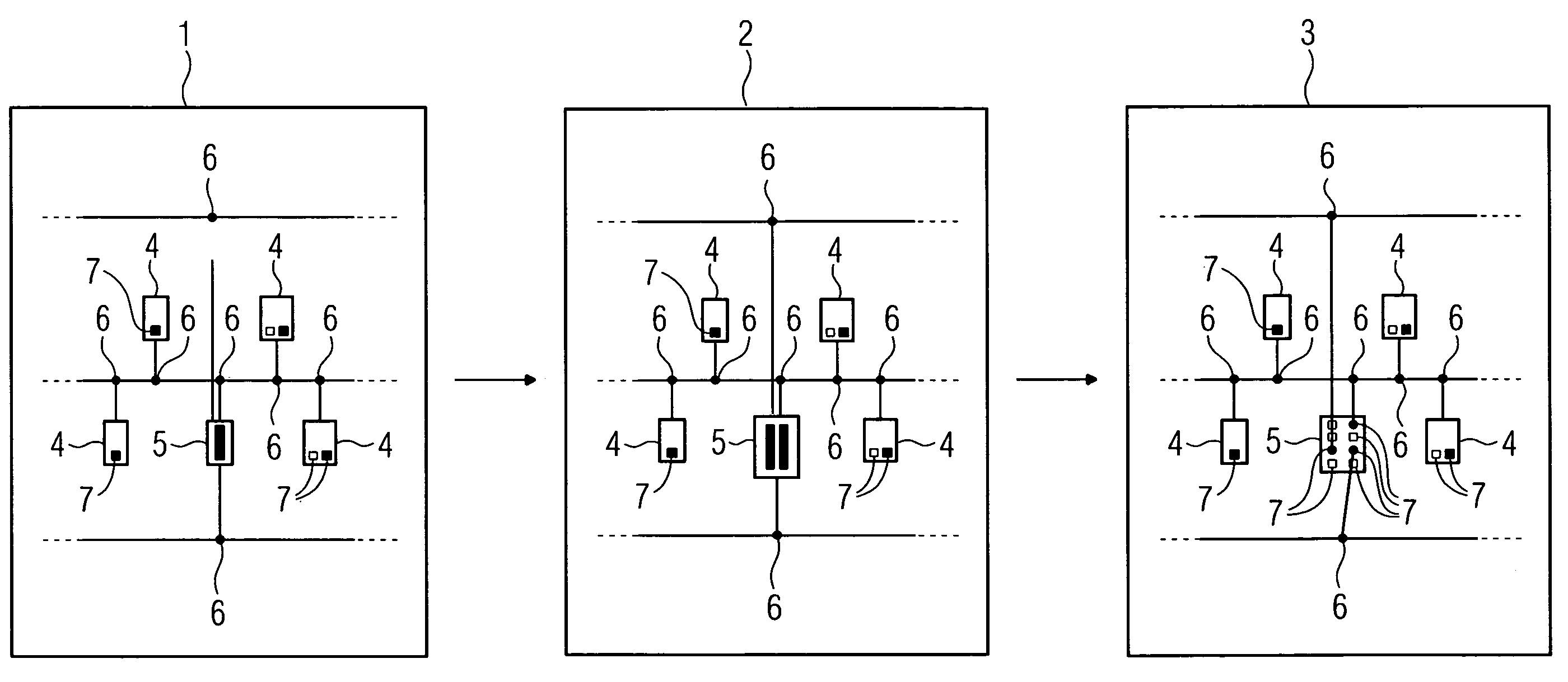
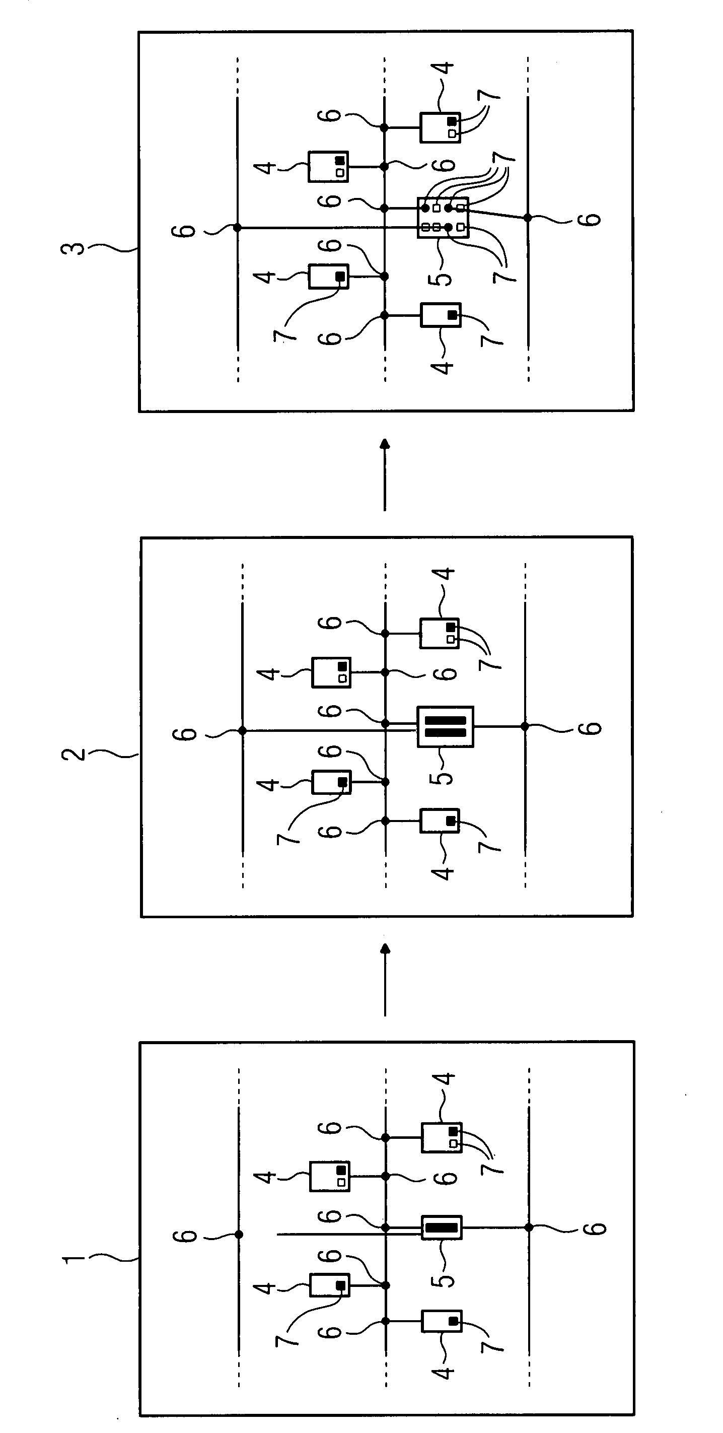
[0022]The left-hand part of FIG. 1 shows in an overview 1 a network of devices 4, 5 of an automation system which each comprise at least one network interface 7. The devices 4, 5 are connected to the network lines by connecting lines which are provided with a marking 6 at the end connected to the network line. The network interfaces 7 can already be seen in the devices 4 in the overview 1. Device 5 on the other hand comprises more network interfaces 7 than can be displayed in this view 1. Device 5 has therefore been selected by a user for enlargement. After activating the display of the detailed view 3 of the selected device 5 a temporary view is displayed in a transition phase 2. In the detailed view 3 the device 5 is presented on a much larger scale than it would be displayed in the view 1 on the basis of its “importance” and its physical size. The consequence of this is that graphical elements, such as adjacent devices 4 or network lines, are sometimes concealed by the device 5 d...


PUM


Abstract

There is described a method, to a program and to a system for graphically displaying and projecting at least one network of devices of an automation system, a high density of information usually occurring at the user interface. To allow a user to selectively display devices in a network, in addition to a large quantity of overview information, a solution is proposed in which a user can display individual devices in more detail in an overview. The user can therefore select a device, the instantaneously non-visible details of which he wishes to access, and change the appearance of the device from a not very detailed display to a very detailed display by way of further interaction. This applies to any desired number of devices which can be simultaneously displayed in detail. One advantage is that the network interfaces of devices may also be displayed which cannot be displayed with all network interfaces in the overview without the user being forced to have to change to a different, detail-oriented view.

Description

CROSS REFERENCE TO RELATED APPLICATIONS [0001]This application claims priority of European Patent Office application No. 06019816.5 EP filed Sep. 21, 2006, which is incorporated by reference herein in its entirety.FIELD OF INVENTION[0002]The invention relates to a method, to a program and to a system for graphically displaying and engineering at least one network of devices of an automation system.BACKGROUND OF INVENTION[0003]A method or program or system of this kind is used in graphically displaying and engineering large networks in an automation environment where there is usually a high density of information at the user interface. High information densities are difficult for an operator or user to capture, i.e. there is a need to keep them low (central usability approach). A common main requirement lies in presenting the user with a large quantity of overview information. Specifically this means that it must be possible to display an overview of one or more network(s) (a large n...

Claims


Application Information

Patent Timeline
IPC IPC(8): G06F3/048
CPCG05B19/41885H04L41/12H04L41/22G05B2219/31098Y02P90/02
Inventor EICHNER, INGO
Owner SIEMENS AG
Why Eureka
Try Eureka