Plasma display device
- Summary
- Abstract
- Description
- Claims
- Application Information
AI Technical Summary
Benefits of technology
Problems solved by technology
Method used
Image

Examples
first embodiment
1. First Embodiment
1-1. Structure of Plasma Display Device
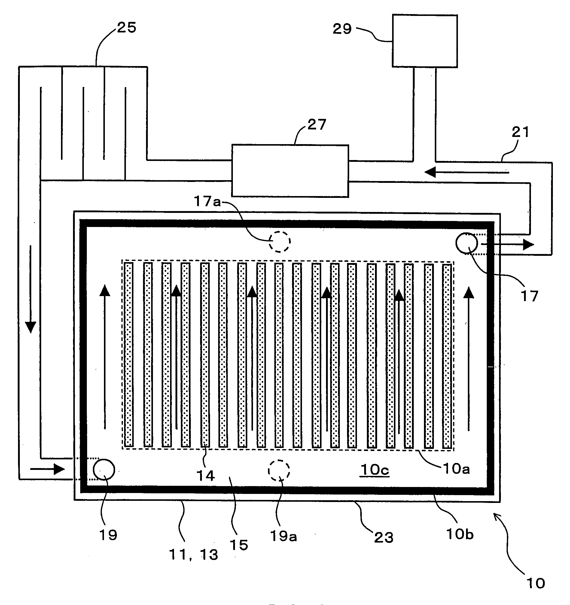
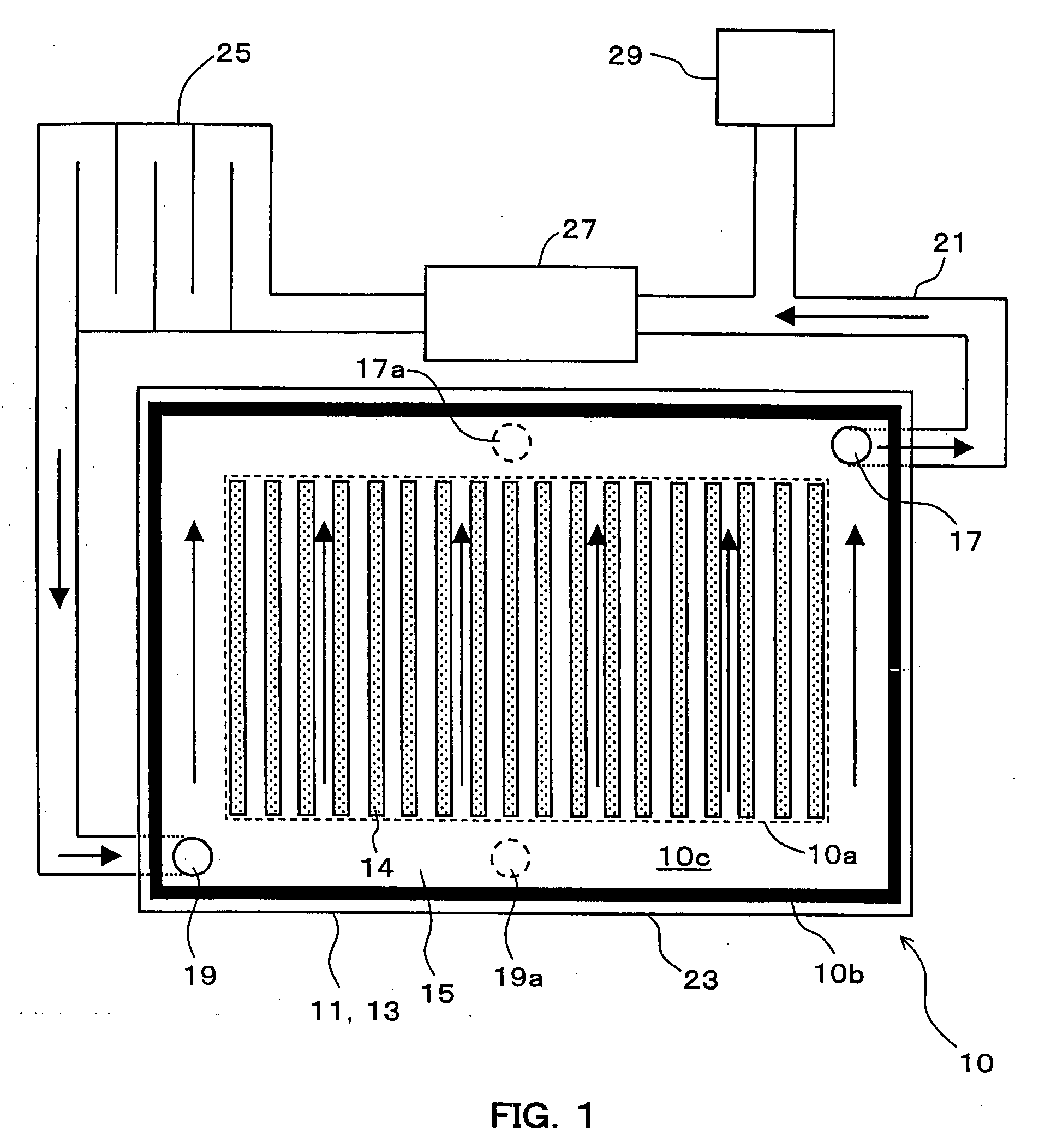
[0034]The structure of a plasma display device of a first embodiment of the invention will be described with reference to FIG. 1. FIG. 1 is a plan view from the front side of a plasma display device of the embodiment.
[0035]The plasma display device of the embodiment has a PDP 10 having a discharge space 15 filled with a discharge gas. The discharge space 15 is formed inside of the PDP 10 formed of a front-side substrate assembly 11 and a rear-side substrate assembly 13 bonded to each other. The PDP 10 has a first hole 17 and a second hole 19 each extending to the discharge space 15. The first and second holes 17 and 19 are coupled to each other via a pipe 21 outside the PDP 10. In a normal mounting state of the PDP 10, the first hole 17 is in a position higher than the second hole 19. The PDP 10 has a rectangular shape, and the normal mounting state is a state where the PDP 10 is upright with its one of long sides 23 down.
[00...
second embodiment
2. Second Embodiment
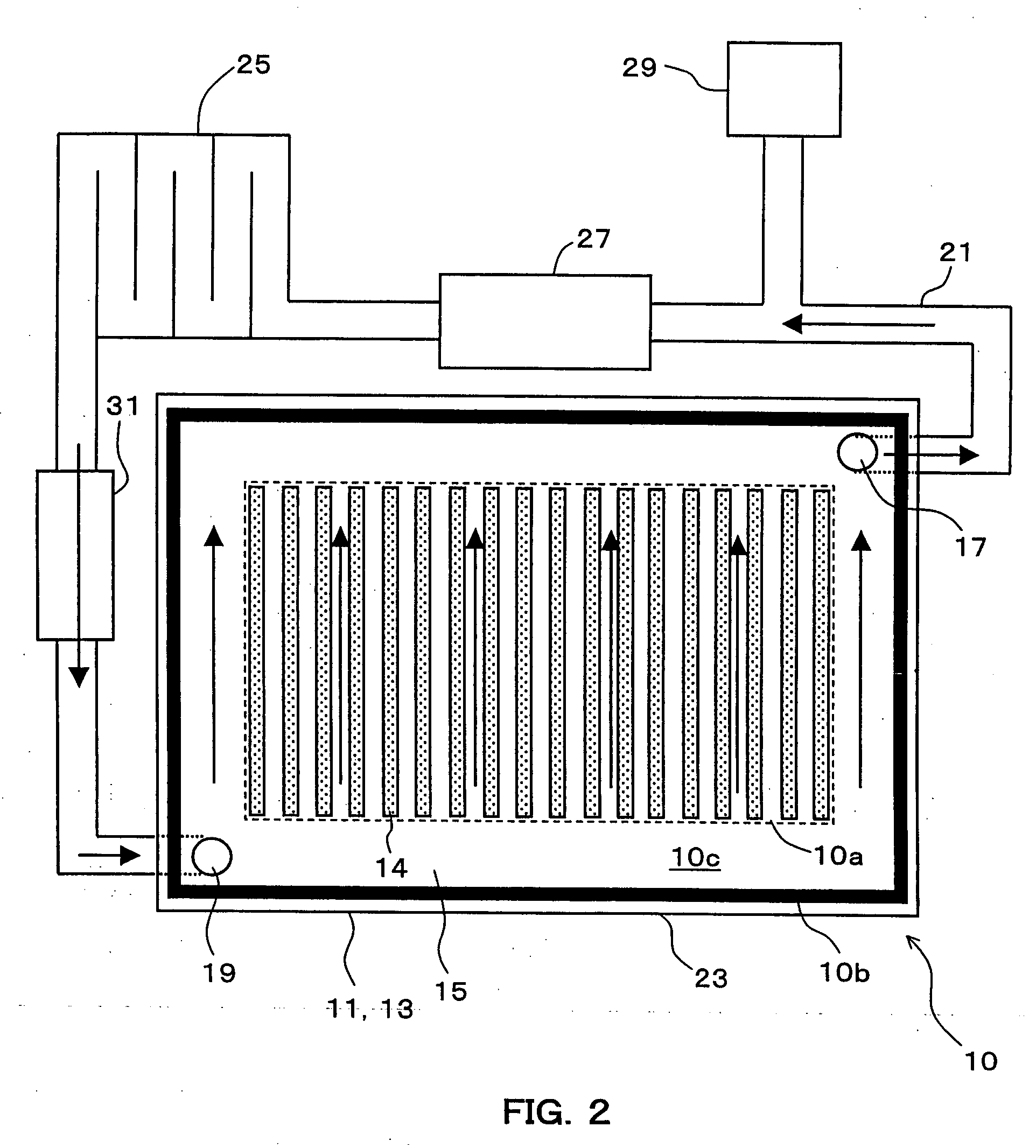
[0051]The structure of a plasma display device of a second embodiment of the invention will be described with reference to FIG. 2. FIG. 2 is a plan view from the front side of a plasma display device of the embodiment.
[0052]The plasma display device of the second embodiment is similar to that of the first embodiment except for the point that a gas circulating mechanism 31 for making the discharge gas circulate in the pipe 21 is provided. In the second embodiment, the discharge gas migrates in the pipe 21 by the action of the gas circulating mechanism 31. Consequently, the first hole 17 does not have to be in a position higher than the second hole 19 in the normal mounting state. The first and second holes 17 and 19 may be at the same height, or the second hole 19 may be in a position higher than the first hole 17. Configuration of the gas circulating mechanism 31 is not limited as long as the gas circulating mechanism 31 have the function of making the discharge ...
third embodiment
3. Third Embodiment
[0054]The structure of a plasma display device of a third embodiment of the invention will be described with reference to FIG. 3. FIG. 3 is a plan view from the front side of a plasma display device of the embodiment.
[0055]The plasma display device of the third embodiment is similar to that of the second embodiment except for the point that the first hole 17 comprises plural portions (five in FIG. 3) provided in the intermediate area 10c in the upper part of the PDP 10 in the normal mounting state of the PDP 10 and the second hole 17 comprises plural portions (five in FIG. 3) provided in the intermediate area 10c in the lower part of the PDP 10 in the normal mounting state of the PDP 10. The plural portions of the first hole 17 and the plural portions of the second hole 19 are connected to the same pipe 21. Further, the plural portions of the first hole 17 are disposed so that an interval of the portions is even, and the plural portions of the second hole 19 are d...
PUM
 Abstract
Description
Claims
Application Information
 - R&D
- Intellectual Property
- Life Sciences
- Materials
- Tech Scout
- Unparalleled Data Quality
- Higher Quality Content
- 60% Fewer Hallucinations
Browse by: Latest US Patents, China's latest patents, Technical Efficacy Thesaurus, Application Domain, Technology Topic, Popular Technical Reports.
© 2025 PatSnap. All rights reserved.Legal|Privacy policy|Modern Slavery Act Transparency Statement|Sitemap|About US| Contact US: help@patsnap.com