
System and method for observing a satellite using a satellite in retrograde orbit

a satellite and retrograde orbit technology, applied in the field of satellites, can solve the problems of limiting the ability to collect high-resolution imagery, difficult to collect information from ground-based assets and leo, and periodic problems of geosynchronous satellites,

Active Publication Date: 2008-04-03
RAYTHEON CO
View PDF99 Cites 41 Cited by
  • Summary
  • Abstract
  • Description
  • Claims
  • Application Information

AI Technical Summary

Benefits of technology

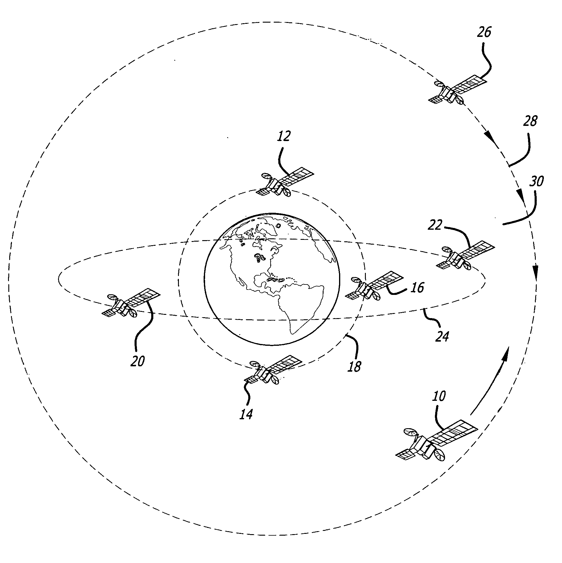
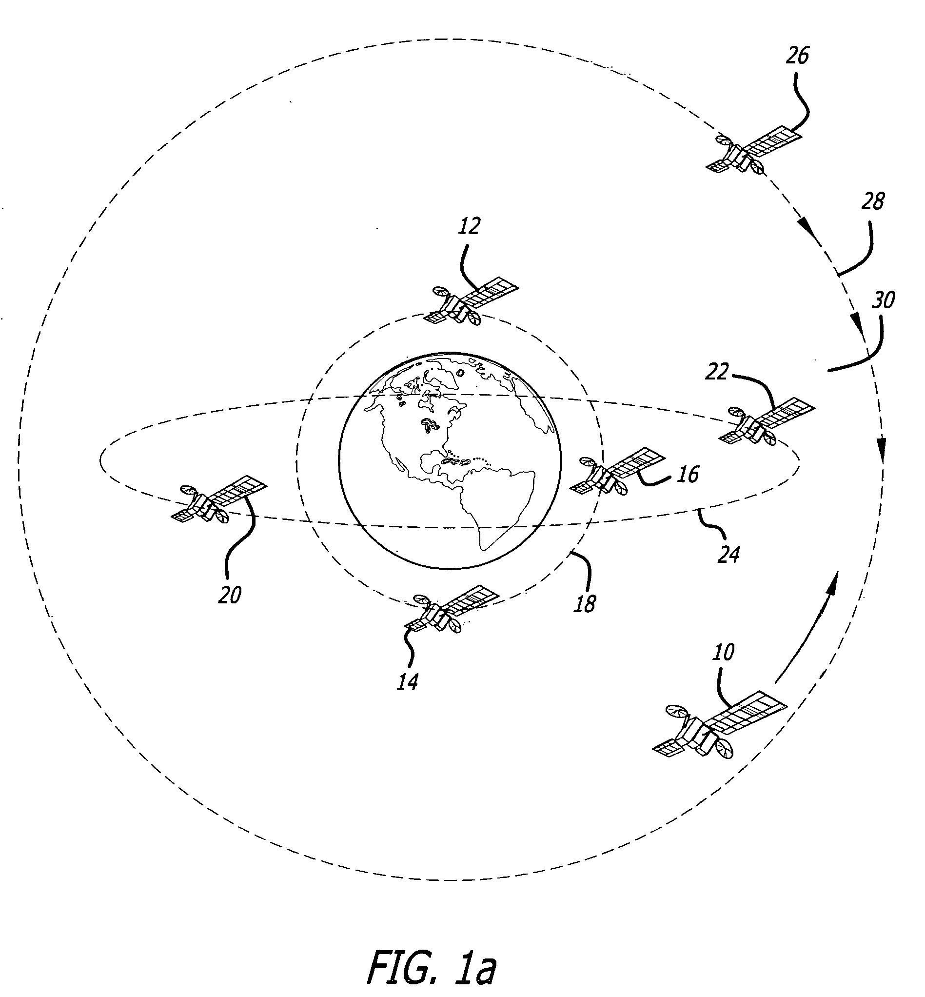
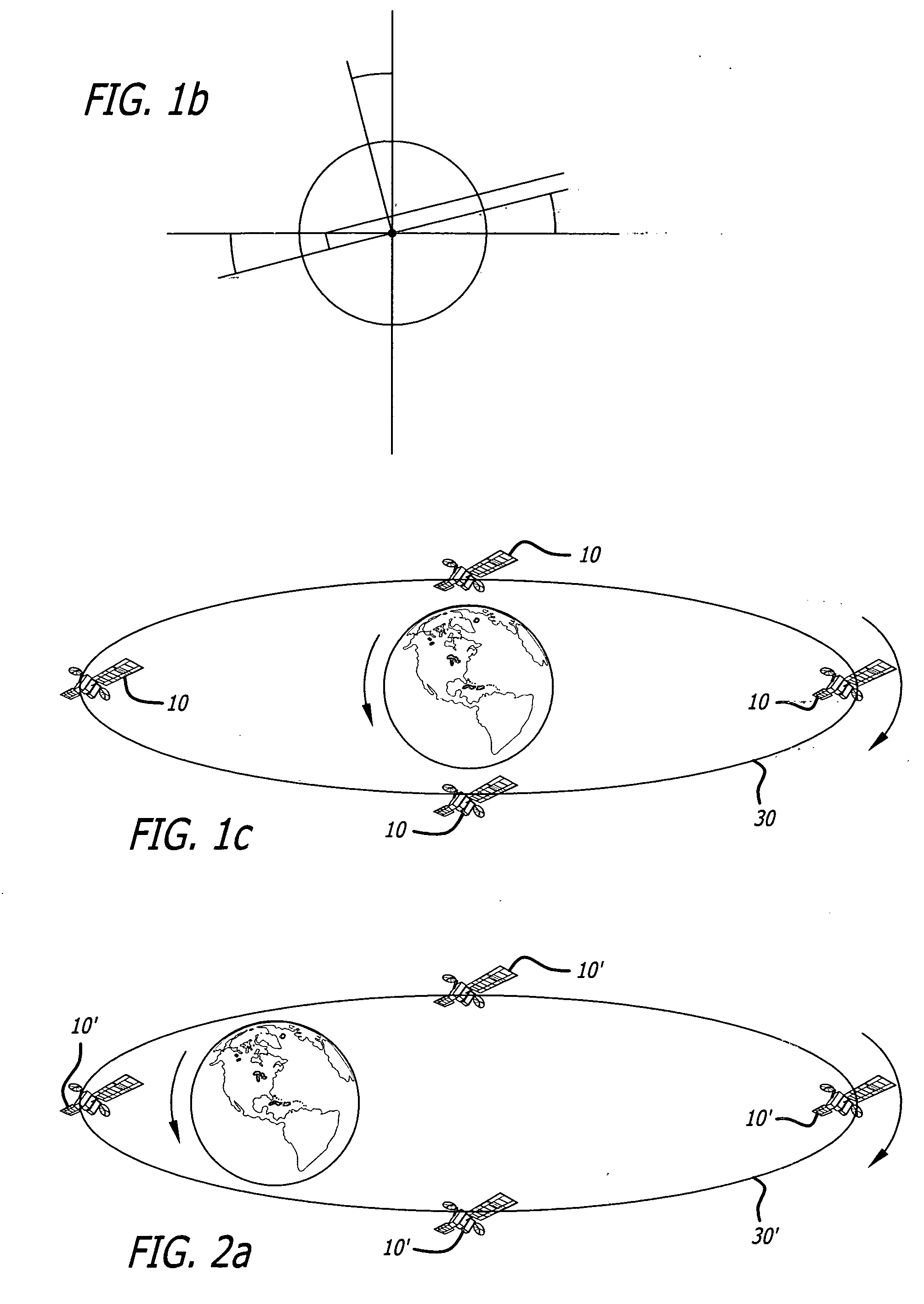
[0011]The invention is well-suited for an illustrative satellite inspection application. In this embodiment, the system includes one or more satellites; means disposed on each satellite for receiving electromagnetic energy from objects (e.g. satellites) within a field-of-view thereof; and an arrangement for placing the inspection satellites in a retrograde orbit. The satellites may be equally spaced

Problems solved by technology

Geosynchronous satellites periodically encounter problems and anomalies and are also subject to attack.
Unfortunately, collection of information from ground-based assets and LEO is difficult for satellites at long range.
Ground-based electro-optic assets can detect some objects at this altitude, but telescope sizes limit the ability to collect high-resolution imagery.
However, the extremely small ground velocity of most satellites at GEO makes this difficult or impossible in practice.
That is, the nearly coincident orbits of the observer and target satellites result in time periods on the order of hours to collect synthetic aperture imagery and do not enable collection of information large numbers of satellites.
It is also difficult to maintain optimal range separation for imaging while controlling relative velocity due to orbital dynamics.
Hence, it would take a long time to observe a large number of satellites.

Method used


Image

  • System and method for observing a satellite using a satellite in retrograde orbit
  • System and method for observing a satellite using a satellite in retrograde orbit
  • System and method for observing a satellite using a satellite in retrograde orbit

Examples


Embodiment Construction

[0019]Illustrative embodiments and exemplary applications will now be described with reference to the accompanying drawings to disclose the advantageous teachings of the present invention.

[0020]While the present invention is described herein with reference to illustrative embodiments for particular applications, it should be understood that the invention is not limited thereto. Those having ordinary skill in the art and access to the teachings provided herein will recognize additional modifications, applications, and embodiments within the scope thereof and additional fields in which the present invention would be of significant utility.

[0021]Systems and methods for placing satellites in orbit are well-known in the art. See, for example, U.S. Pat. No. 6,182,928 entitled METHOD FOR PLACING AN ARTIFICIAL SATELLITE ON A GEOSTATIONARY ORBIT, issued Feb. 6, 2001 to A. Wagner; U.S. Pat. No. 6,128,575 entitled METHODS FOR ACCURATELY INSERTING SATELLITE CONSTELLATIONS INTO COMMON ORBIT PLAN...


PUM


Abstract

A satellite and an arrangement for placing the satellite in a retrograde orbit, i.e. inclined at approximately 180° to the equator. Multiple satellites may be used and the orbits thereof may be circular or elliptical. The invention is well-suited for an illustrative satellite inspection application. In this embodiment, the system includes one or more satellites; means disposed on each satellite for receiving electromagnetic energy from objects (e.g. satellites) within a field-of-view thereof; and an arrangement for placing the inspection satellites in a retrograde orbit. The satellites may be equally spaced in a single orbit or disposed in equally spaced orbits. The satellites may include a variety of instruments including radar, infrared, visible, etc. In a radar implementation, the satellite may include a bistatic or (with a transmitter) monostatic radar system. In the bistatic case, the signal may be transmitted from a ground-based or space based platform.

Description

BACKGROUND OF THE INVENTION[0001]1. Field of the Invention[0002]The present invention relates to satellites. More specifically, the present invention relates to systems and methods for observing and inspecting satellites.[0003]2. Description of the Related Art[0004]A considerable investment has been made to place satellites in geosynchronous orbit (GEO) to perform a variety of functions. Geosynchronous satellites are satellites with an orbital track on the Earth that repeats regularly over points on the Earth over time. Geosynchronous satellites located at the equator appear stationary over the Earth and hence are referred to as ‘Geostationary’.[0005]Geosynchronous satellites periodically encounter problems and anomalies and are also subject to attack. Hence, there is a need to inspect geosynchronous satellites and other objects in space to determine the status thereof. This may include detection and resolution of anomalies on spacecraft. Detecting new objects, verifying the positio...

Claims


Application Information

Patent Timeline
IPC IPC(8): H04B7/185H04Q7/20
CPCH04B7/18519
Inventor ROBINSON, IAN S.
Owner RAYTHEON CO
Learn More