Multi-satellite navigation system compatible GNSS (Global Navigation Satellite System) signal receiving method and correlator thereof
A satellite navigation system and signal receiving technology, applied in the field of satellite communication, can solve the problem of not being able to receive satellite signals, etc.
- Summary
- Abstract
- Description
- Claims
- Application Information
AI Technical Summary
Problems solved by technology
Method used
Image
Examples
no. 1 example
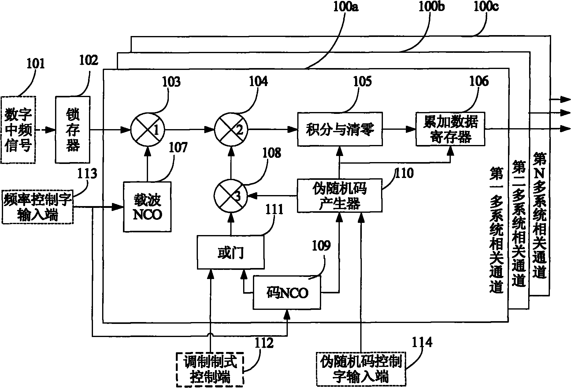
[0166] figure 1 It is a structural block diagram of the correlator in the present invention. The correlator consists of multiple independent correlation channels 100a, 100b and 100c and a latch such as figure 1 The shown 100a, 100b and 100c respectively correspond to different channels, and the structures of different channels are the same, and all relevant channels share one latch 102 . Each multi-system correlation channel consists of a multiplier group (103, 104 and 108) including a multiplier 1, a multiplier 2 and a multiplier 3, an integral and clear circuit 105, an accumulation data register 106, a carrier NCO107, a code NCO109, a pseudo It consists of a random code generator 110 and an OR gate 111 for selecting a modulation system. The intermediate frequency signal input end of multiplier 103 is connected the output end of intermediate frequency signal latch, the carrier signal input end of multiplier 103 is connected the output end of carrier NCO107, and two signal i...
no. 2 example
[0169] figure 2 It is a schematic block diagram of the structure of the carrier NCO according to the embodiment of the present invention. The phase accumulator and its frequency control word in one embodiment of the carrier NCO are both 32-bit wide, and the phase accumulator 202 continuously accumulates the frequency control word. If the accumulated result exceeds the range represented by the 32-bit data, it will automatically overflow and continue add up. The frequency control word 201 is connected to the input end of the phase accumulator 202, and the accumulating step size of the phase accumulator 202 is controlled by the bit width of the frequency control word. The output terminal of the phase accumulator 202 is connected to the sine wave mapping table 203. After the phase accumulator 202 accumulates each time, its upper 3 bits are used as the quantized phase, and are output to the sine wave mapping table 203 to obtain the corresponding sine value and The sine value wit...
no. 3 example
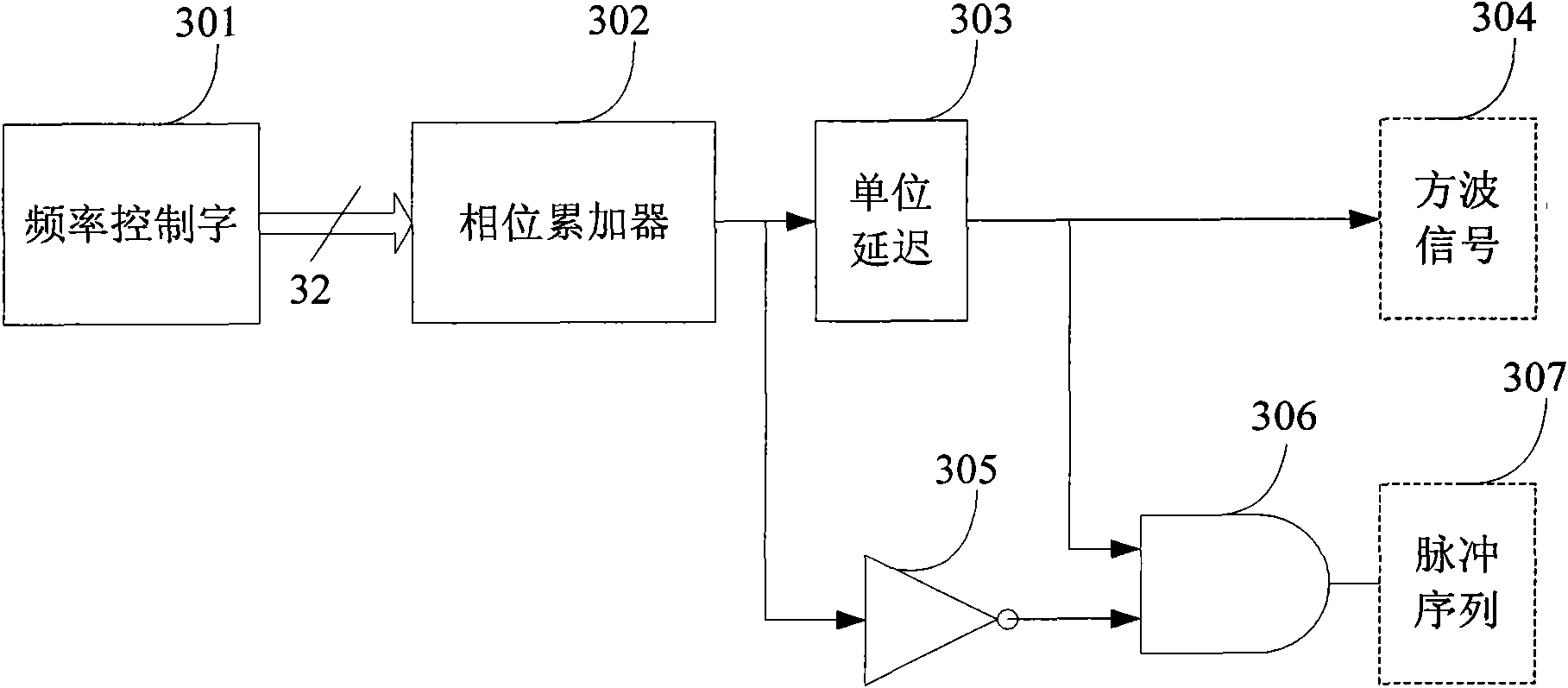
[0171] image 3 It is a schematic block diagram of the structure of the code NCO of the embodiment of the present invention. The phase accumulator and its frequency control word in one embodiment of the code NCO are all 32-bit wide, and the frequency control word 301 is connected to the input end of the phase accumulator 302, and controls the accumulation step of the phase accumulator 302 with the frequency control word bit width long. The 302 phase accumulator continuously accumulates the frequency control word. If the accumulated result exceeds the range represented by the 32-bit data, it will automatically overflow and continue to accumulate. The frequency control word 301 determines the accumulation step size of the phase accumulator 302, and controls the data overflow frequency of the phase accumulator, that is, the inversion frequency of the highest bit of the phase accumulator, that is, the sign bit. The output terminal of the phase accumulator 302 is connected to the...
PUM
 Abstract
Description
Claims
Application Information
 - R&D
- Intellectual Property
- Life Sciences
- Materials
- Tech Scout
- Unparalleled Data Quality
- Higher Quality Content
- 60% Fewer Hallucinations
Browse by: Latest US Patents, China's latest patents, Technical Efficacy Thesaurus, Application Domain, Technology Topic, Popular Technical Reports.
© 2025 PatSnap. All rights reserved.Legal|Privacy policy|Modern Slavery Act Transparency Statement|Sitemap|About US| Contact US: help@patsnap.com


