Method of determining and controlling the inertial attitude of a spinning, artificial satellite and systems therefor

a technology of inertial attitude and artificial satellite, applied in the direction of navigation instruments, instruments for comonautical navigation, instruments, etc., can solve the problems of radiation susceptibility and temperature susceptibility, and achieve the effects of reducing material bulk, high gain, and high bandwidth capacity

Inactive Publication Date: 2009-09-03
JOHNSON KARA WHITNEY +1
View PDF11 Cites 36 Cited by
  • Summary
  • Abstract
  • Description
  • Claims
  • Application Information

AI Technical Summary

Benefits of technology

[0019]The low-light-level EBCMOS optical sensor uses the feature of Electronic Bombardment (EB) in which a local high voltage provides a gain greater than 100, i.e., 100 electrons output per each photon at the photocathode. This high gain enables the “thinning” of the photocathode—thus reducing the bulk of material where deleterious radiation effects occur. The lost sensitivity at the photocathode is recovered with the extremely high gain, resulting in superior sensitivity, noise performance, bandwidth capability, and other sensor performance measures.
[002

Problems solved by technology

Additionally, as mentioned above, with regard to reliability of the implementation of space-based instrumentation, additional critical issues t

Method used


Image

  • Method of determining and controlling the inertial attitude of a spinning, artificial satellite and systems therefor
  • Method of determining and controlling the inertial attitude of a spinning, artificial satellite and systems therefor
  • Method of determining and controlling the inertial attitude of a spinning, artificial satellite and systems therefor

Examples


Embodiment Construction

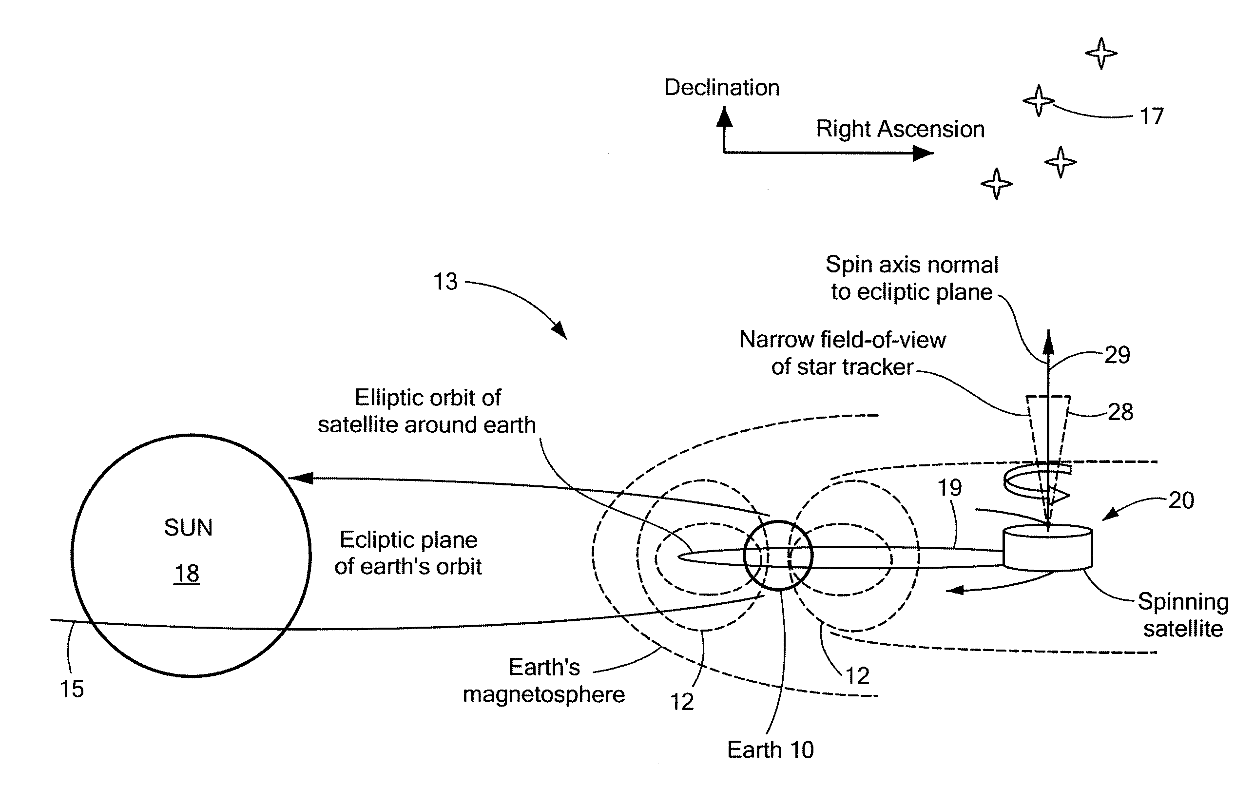
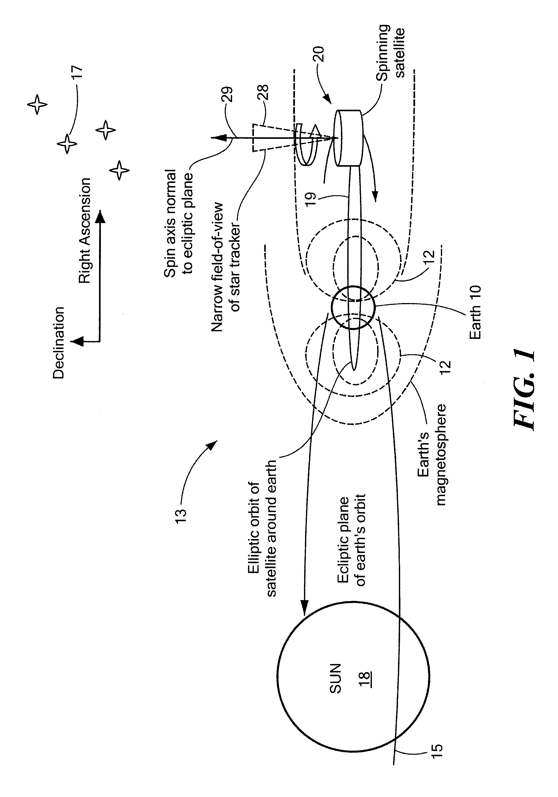
[0039]Methods and systems for accurately determining and controlling the inertial attitude of an artificial satellite, a spinning satellite, a spinning strategic missile, a spinning communication antenna system, a spinning surveillance satellite system, a spinning station-keeping formation system, a spinning scientific measurement satellite system, a spinning astronomical measurement satellite system, and the like (hereinafter, collectively referred to as “an artificial satellite” for brevity) are disclosed. The disclosed methods constitute an improvement to the methods discussed in U.S. Pat. No. 6,577,929 to Johnson, et al., which is incorporated in its entirety herein by reference.

[0040]Briefly, U.S. Pat. No. 6,577,929 discloses methods for measuring the inertial attitude of artificial satellites and, more particularly, for measuring the inertial attitude of spinning, artificial satellites or non-spinning, three-axis stabilized artificial satellites. According to U.S. Pat. No. 6,5...


PUM


Abstract

A method of and apparatus for determining and controlling the inertial attitude of a spinning artificial satellite without using a suite of inertial gyroscopes. The method and apparatus operate by tracking three astronomical objects near the Earth's ecliptic pole and the satellite's and/or star tracker's spin axis and processing the track information. The method and apparatus include steps and means for selecting preferably three astronomical objects using a histogram method and determining a square of a first radius (R12) of a track of a first astronomical object; determining a square of a second radius (R22) of a track of a second astronomical object; determining a square of a third radius (R32) of a track of a third astronomical object; determining the inertial attitude of the spin axis using the squares of the first, second, and third radii (R12, R22, and R32) to calculate pitch, yaw, and roll rate; determining a change in the pitch and yaw of the artificial satellite; and controlling on-board generated current flow to various orthogonally-disposed current-carrying loops to act against the Earth's magnetic field and to apply gyroscopic precession to the spinning satellite to correct and maintain its optimum inertial attitude.

Description

CROSS REFERENCE TO RELATED APPLICATIONS[0001]The present invention is a continuation-in-part application that claims the benefit of U.S. patent application Ser. No. 11 / 818,723 filed on Jun. 15, 2007 having the same title and claims the benefit of priority through U.S. Provisional Patent Application No. 60 / 815,068 dated Jun. 20, 2006 entitled “Spinning Satellite Attitude Control and Determination System”.STATEMENT REGARDING FEDERALLY SPONSORED RESEARCH OR DEVELOPMENT[0002](Not applicable)BACKGROUND OF THE INVENTION[0003]The present invention relates to the field of guidance, navigation, and control avionics, and, more particularly, to an inertial attitude sensing system for a class of ultra-low-power, artificial, spinning satellites designed to be small and light-weight.[0004]Such small, artificial, spinning satellite constellations can collect data using, for example, optical or other sensor instrumentation. Necessarily, these data must be referenced to an inertial attitude sensing ...

Claims


Application Information

Patent Timeline
IPC IPC(8): G05D1/00B64G1/36G01C21/24
CPCB64G1/281B64G1/32B64G1/361G05D1/0883B64G1/365B64G1/44G01S3/7862B64G1/363B64G1/244
Inventor JOHNSON, WILLIAM M.
Owner JOHNSON KARA WHITNEY
Why Eureka
Try Eureka