Medical diagnostic system data exchange method and system

Inactive Publication Date: 2008-04-03
GENERAL ELECTRIC CO
View PDF7 Cites 10 Cited by
  • Summary
  • Abstract
  • Description
  • Claims
  • Application Information

AI Technical Summary

Problems solved by technology

For example, existing solutions do not provide an immediate response mechanism that can address pressing needs at the systems.
Similarly, while many problems could be addressed immediately by a service engineer or a field engineer, there is not at present a mechanism on the systems to contact the appropriate personnel for the immediate service

Method used


Image

  • Medical diagnostic system data exchange method and system
  • Medical diagnostic system data exchange method and system
  • Medical diagnostic system data exchange method and system

Examples


Embodiment Construction

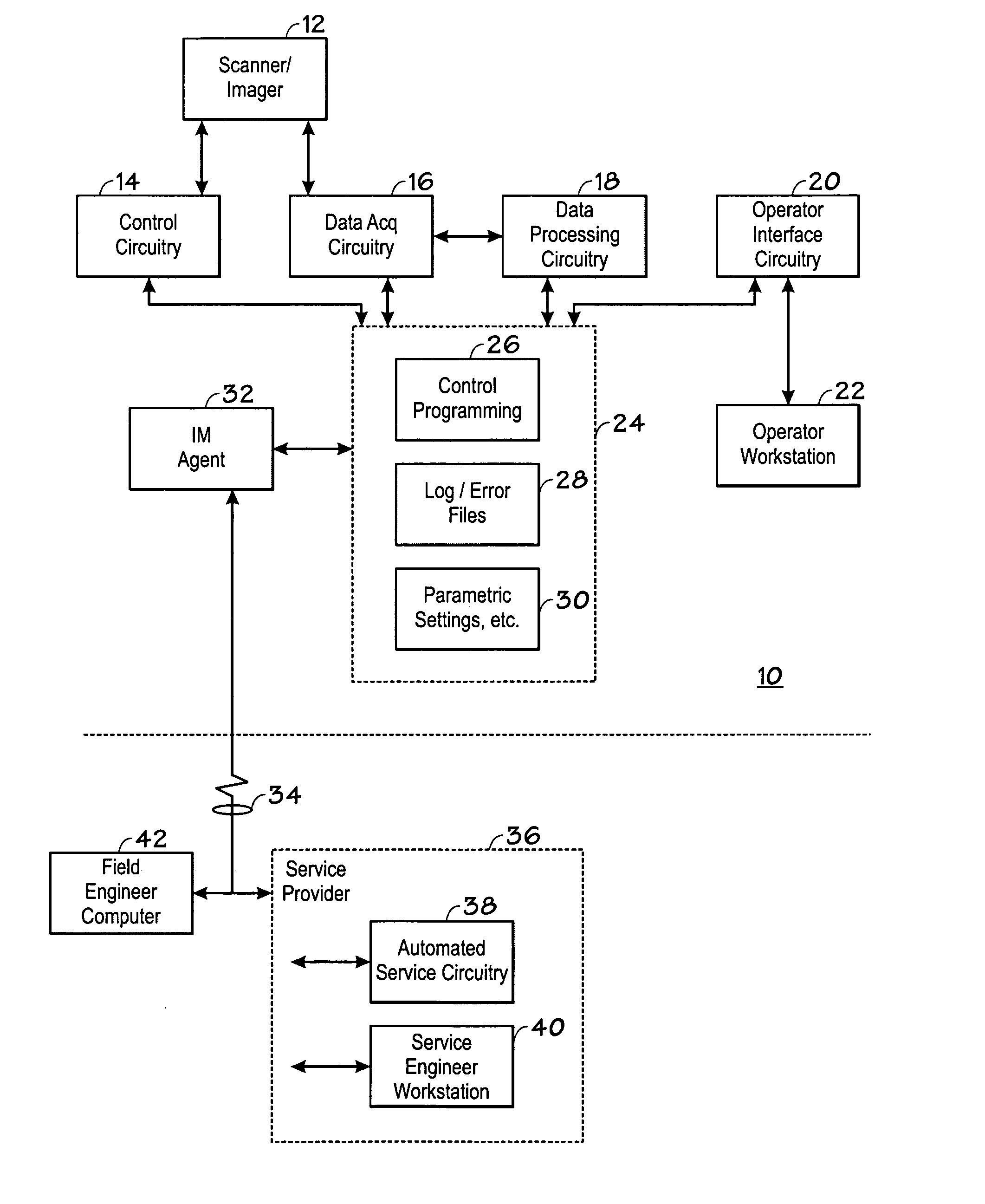
[0014]Turning now to the drawings, and referring first to FIG. 1, an IM-equipped medical diagnostic system data exchange system is illustrated and designated generally by the reference numeral 10. In the illustrated embodiment, the system includes a medical diagnostic imaging system, sometimes referred to as a scanner or imager 12. As will be appreciated by those skilled in the art, the scanner / imager 12 may include any suitable modality system, such as ultrasound systems, MRI systems, CT and X-ray systems, PET imaging systems, and so forth. The scanner / imager will generally be capable of creating image data of a subject of interest based upon the physics of its particular modality. The imager / scanner 12 operates under the control of control circuitry 14 which will typically initiate scanning sequences, implement particular scanning protocols, and regulate the acquisition of image data that will be digitized for reconstruction of useful images. Data acquisition circuitry 16, then, r...


PUM


Abstract

A technique is disclosed for exchanging data between a medical diagnostic imaging system and a remote service provider. The system includes the use of an instant messaging (IM) agent stored an operative on the imaging system and at the remote service provider. A human operator at the imaging system may initiate an IM session with the service provider, or such sessions may be initiated either by the service provider or automatically by the imaging system or by computers at the service provider. The IM session may include the exchange of service data, log files, error files, as well as general information on the operation and servicing of the imaging system. The IM session may supplement or replace telephonic exchanges, electronic messages, or even certain personal visits by service engineers.

Description

BACKGROUND[0001]The present invention relates generally to the field of medical diagnostic systems. More particularly, the invention relates to a technique for communicating information to and from such systems via an instant messaging agent.[0002]Over recent years medical diagnostic imaging equipment has evolved to provide improved connectivity to service providers, remote systems, hospital and clinic networks, and so forth. For example, many fixed medical diagnostic imaging systems were at one time equipped with communications circuitry that permitted them to be contacted from a service provider so as to detect or extract data regarding operation of the system. In many cases, the system operators were themselves unaware that such contacts were being made, with service providers ensuring the good operating condition of the systems with minimal intervention by the operators. Later evolution in such connectivity solutions included the provision of browsers and similar interfaces on i...

Claims


Application Information

Patent Timeline
IPC IPC(8): A61B5/05G16H30/20G16H40/67
CPCG06F19/3418G06F19/321G16H40/67G16H30/20
Inventor SOLLIDAY-MCROY, JEFFREY DALE
Owner GENERAL ELECTRIC CO
Why Eureka
Try Eureka