Manufacturing System and Method

a manufacturing system and monitoring system technology, applied in the field of control and/or monitoring systems, can solve the problems of inability to operate in the presence of high-energy electromagnetic fields, inability to accurately and reliably and inability to accurately detect the presence of electromagnetic fields

Inactive Publication Date: 2008-04-03
ROCKWELL AUTOMATION TECH
View PDF7 Cites 10 Cited by
  • Summary
  • Abstract
  • Description
  • Claims
  • Application Information

AI Technical Summary

Benefits of technology

[0008]The present inventors have recognized that an improved automated manufacturing system employing one or more process controllers can be achieved by providing an additional intermediate control device that is coupled between at least one of the process controllers and one or more sensors of the automated manufacturing system. In at least some embodiments, the intermediate control device is physically positioned sufficiently remotely from one or more sources of manufacturing-related stresses such that the intermediate control device is substantially less likely to suffer damage than the sensors, which are positioned more closely to the sources of manufacturing-related stresses.

Problems solved by technology

Conventional sensors often have complicated designs that allow the sensors to achieve high accuracy and reliability, and to perform a variety of functions.
Although the accuracy and reliability of today's sensors is often quite high, the performance of such sensors can still be adversely affected when the sensors are exposed to the stresses of a manufacturing process, for example, high or low temperatures, high or rapid temperature fluctuations, physical impacts or impulses, or high-energy electromagnetic fields as are generated in some manufacturing processes, such as those associated with automotive welding operations.
In the context of ferrite-core inductive sensors in particular, such sensors typically are unable to operate in the presence of high-energy electromagnetic fields such as those created during welding operations, due to saturation of the ferrite cores in the sensors.
While some inductive proximity sensors termed “weld field immune” (WFI) sensors have been designed to operate during the presence of high-energy electromagnetic fields, such sensors have sensing ranges that are limited.
This, however, tends to increase the likelihood that the sensors will be damaged over time due to exposure to various physical hazards, for example, due to impacts from components undergoing manufacturing (e.g., an auto body) or contact with damaging materials during a manufacturing process (e.g., weld slag hitting the sensor).
Given their complexity, the sensors employed in automated manufacturing systems can be expensive.
Therefore, as the multiple sensors employed in an automated manufacturing system occasionally malfunction or break over time due to their repeated exposure to manufacturing-related stresses, the costs associated with the replacement or repair of sensors can become undesirably high.
Yet even more disadvantageous than the costs of replacing or fixing damaged sensors in an automated manufacturing system is the fact that, when sensors become damaged, the sensors often will no longer provide appropriate output signals, which can disrupt the operation of the entire system (or at least a significant portion of the system) and / or cause significant delays in the performance of the automated manufacturing process.
However, once a signal that is contradictory to an expected state is received from any one or more of the sensors, the controller typically will cause the process under its control to stop.
Consequently, repeated process stoppages can occur as one or more of the sensors malfunction or break, which in turn can result in delays that significantly reduce the efficiency and output of the process.

Method used


Image

  • Manufacturing System and Method
  • Manufacturing System and Method
  • Manufacturing System and Method

Examples


Embodiment Construction

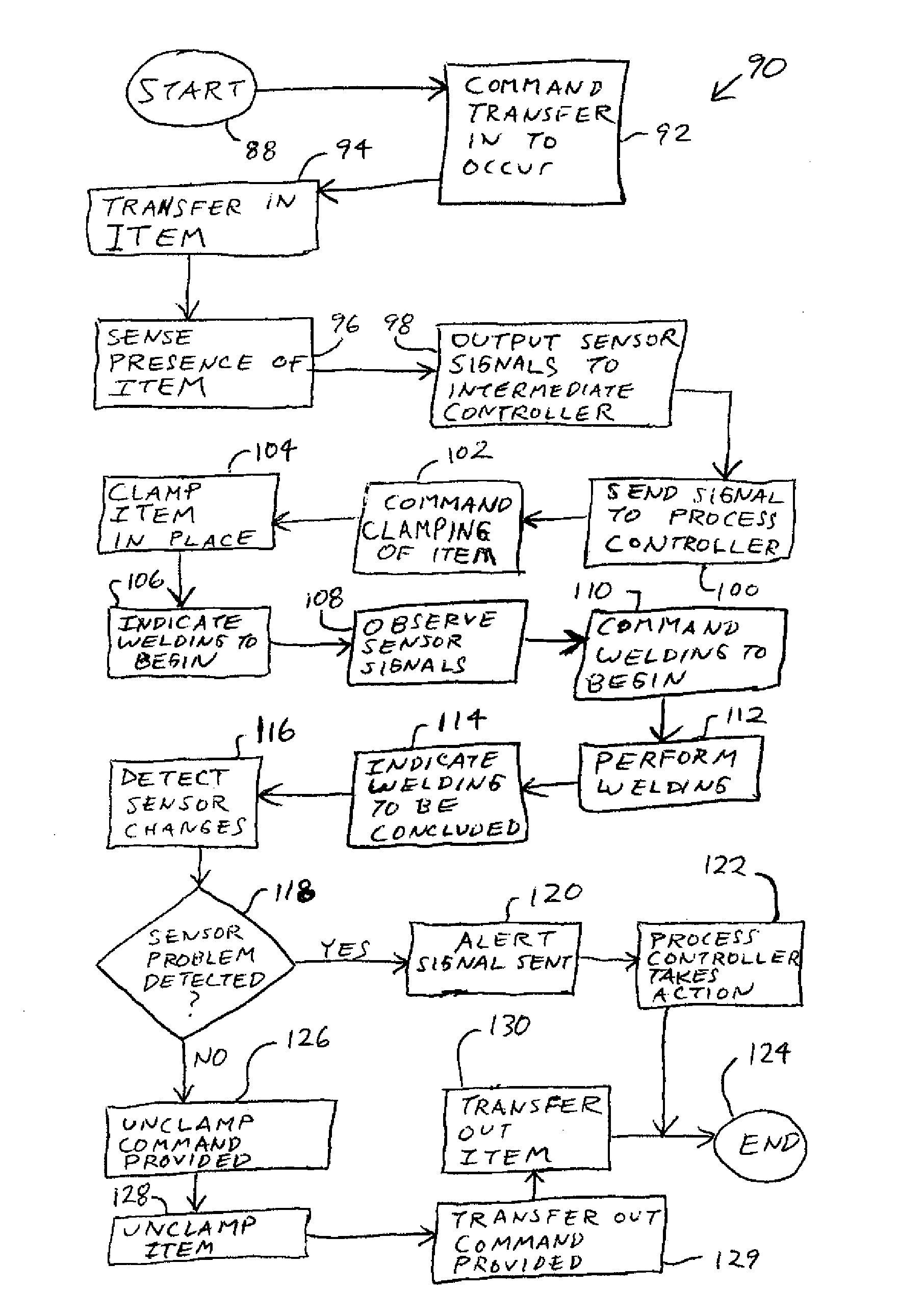
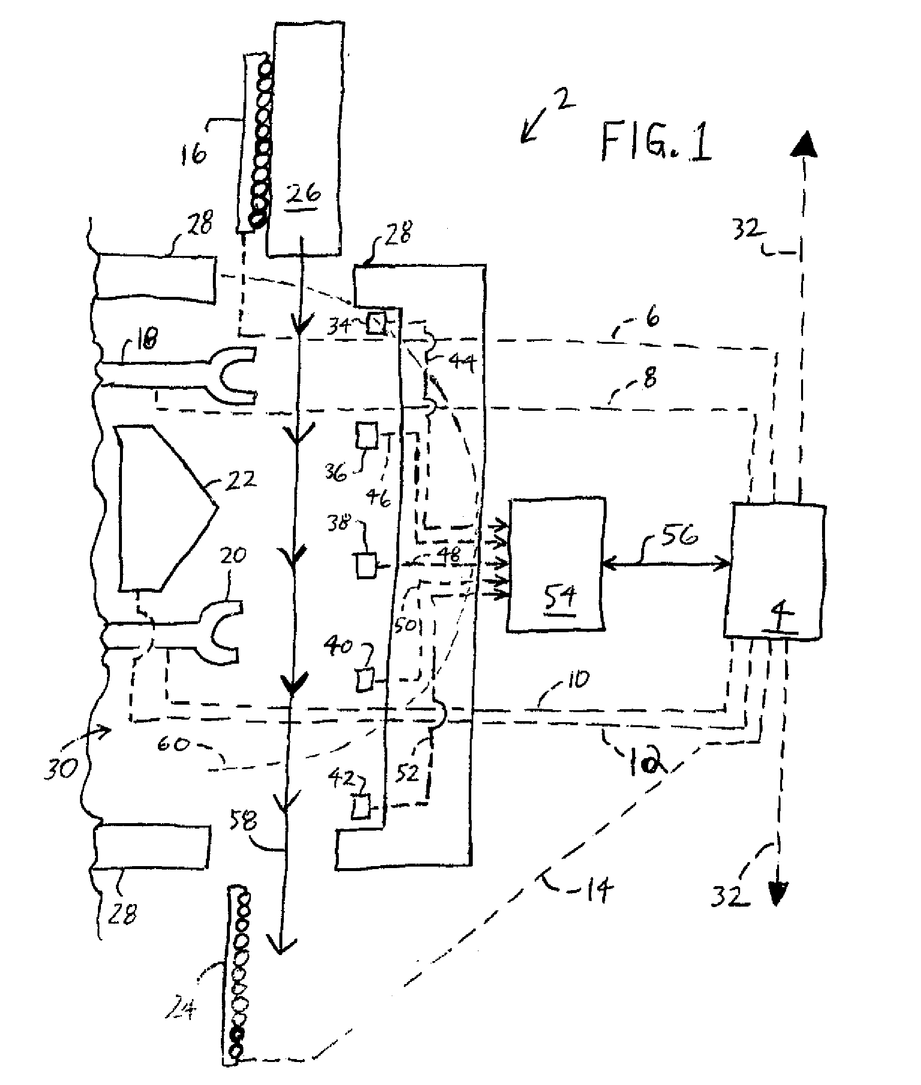
[0017]Referring to FIG. 1, an exemplary automated manufacturing system 2 in accordance with at least one embodiment of the present invention is shown in schematic form. The automated manufacturing system 2 performs an automated manufacturing process, which in the present embodiment is a welding process such as that employed during the manufacture of automobiles, as described in further detail below with reference to FIG. 4. Thus, in the present embodiment, the automated manufacturing system 2 is an automotive welding system or a portion of such a system. Depending upon the embodiment, the automated manufacturing system 2 that is shown in FIG. 1 can constitute only a subportion of a larger system. For example, the welding operation performed by the system 2 can be only one of multiple welding operations that are performed upon a variety of automotive components that are being assembled with one another. Thus, it should be understood that the automated manufacturing system 2 is intend...


PUM


Abstract

An automated manufacturing system, intermediate control device for implementation in such a system, and method of performing a manufacturing operation are disclosed. In at least some embodiments, the automated manufacturing system includes a first sensor that provides a first output signal, a first controllable device, and a first process controller capable of issuing a first command to the first controllable device. The system further includes a first intermediate control device coupled between the first sensor and the first process controller. The first intermediate control device receives the first output signal and determines, based at least in part upon the first output signal, whether to send an additional signal to the first process controller indicative of a failure condition.

Description

CROSS-REFERENCE TO RELATED APPLICATIONSSTATEMENT REGARDING FEDERALLY SPONSORED RESEARCH OR DEVELOPMENTFIELD OF THE INVENTION[0001]The present invention relates to control and / or monitoring systems, and more particularly to systems employed in controlling and / or monitoring manufacturing processes.BACKGROUND OF THE INVENTION[0002]Many modern manufacturing processes are automated to a high degree. In order for automated manufacturing processes to operate predictably and reliably, the systems used to perform such processes (“automated manufacturing systems”) often employ numerous sensors that are capable of sensing a variety of different components, conditions and / or parameters. Often, multiple sensors are employed collectively in relation to a single step of the manufacturing process.[0003]Conventional sensors often have complicated designs that allow the sensors to achieve high accuracy and reliability, and to perform a variety of functions. For example, many conventional sensors incl...

Claims


Application Information

Patent Timeline
Patent Type & Authority Applications(United States)
IPC IPC(8): G06F19/00
CPCG05B2219/45135G05B19/4184Y02P90/02
Inventor WIESE, GREGORY S.NAIR, SURESH R.
Owner ROCKWELL AUTOMATION TECH
Why Eureka
Try Eureka