Holder Assembly

a technology of holder and assembly, which is applied in the direction of cutting machines, earth drilling and mining, slitting machines, etc., can solve problems such as breakag

Active Publication Date: 2008-04-17
NOVATEK INC
View PDF99 Cites 18 Cited by
  • Summary
  • Abstract
  • Description
  • Claims
  • Application Information

AI Technical Summary

Problems solved by technology

In asphalt milling, a drum supporting an array of picks may rotate such that the picks engage a paved surface causing it to break up.

Method used


Image

  • Holder Assembly
  • Holder Assembly
  • Holder Assembly

Examples


Embodiment Construction

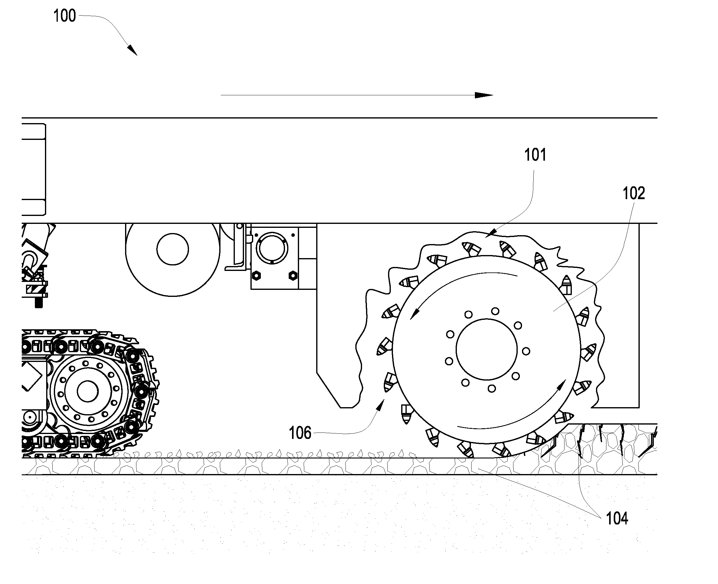
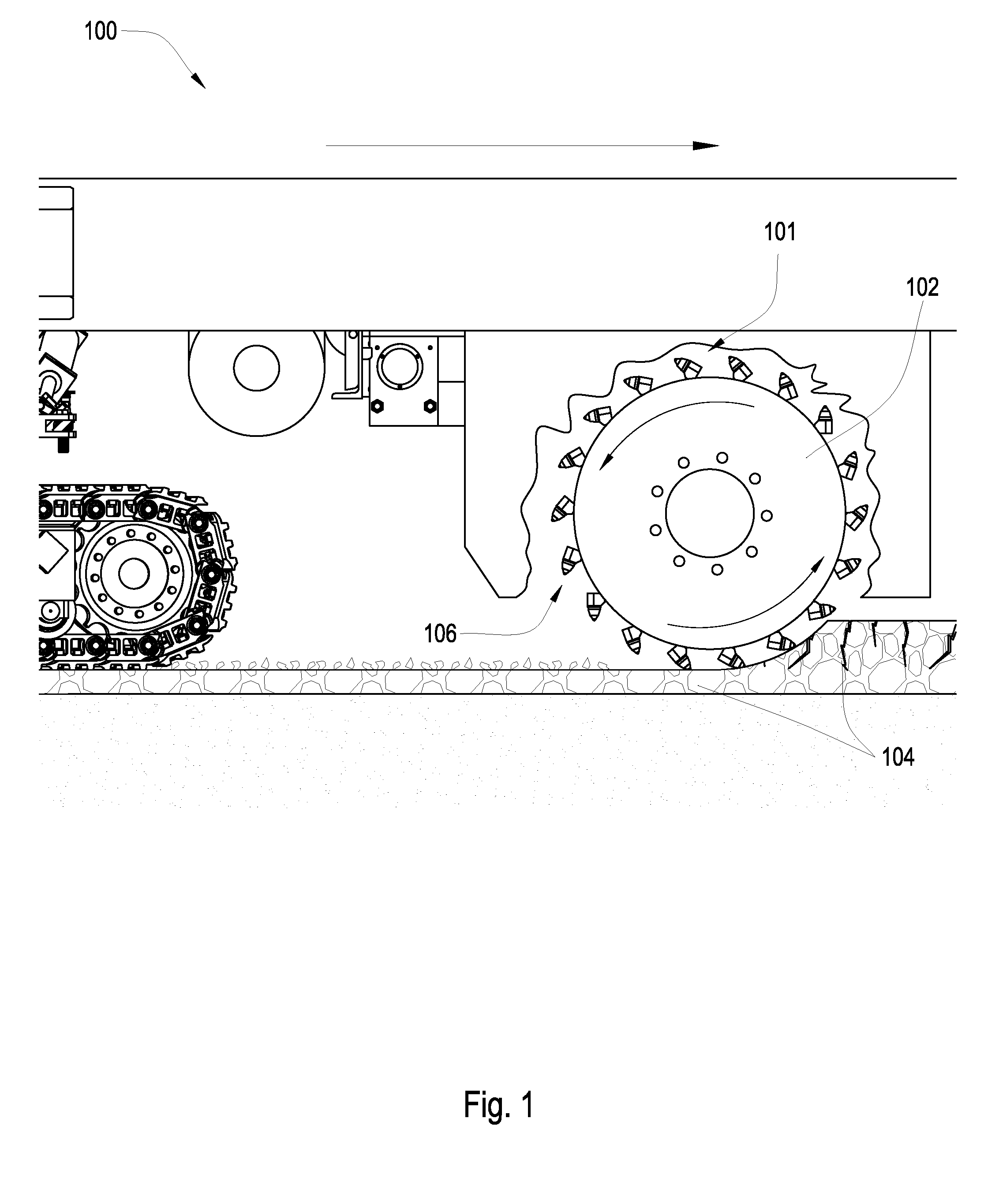
[0021]FIG. 1 is a cross-sectional diagram of an embodiment of a pavement milling machine 100. A plurality of holder assemblies 101 are attached to a rotating drum 102 connected to the underside of a pavement milling machine 100. The milling machine 100 may be a cold planer used to degrade man-made formations such as pavement 104 prior to the placement of a new layer of pavement. Holder assemblies 101 may be attached to the drum 102 at an angle, thereby bringing the holder assemblies 101 into engagement with the formation 104 at the desired level of aggressiveness. A pick 106 may be inserted into a holder assembly 101. As the drum 102 rotates in the direction shown by the arrows, the picks 106 temporarily contact the pavement 104. The impact from this contact causes the degradation of the pavement 104, as well as eventually wearing the picks 106. Drums 102 according to the present invention may also be used in mining machines, trenching machines, and in other applications.
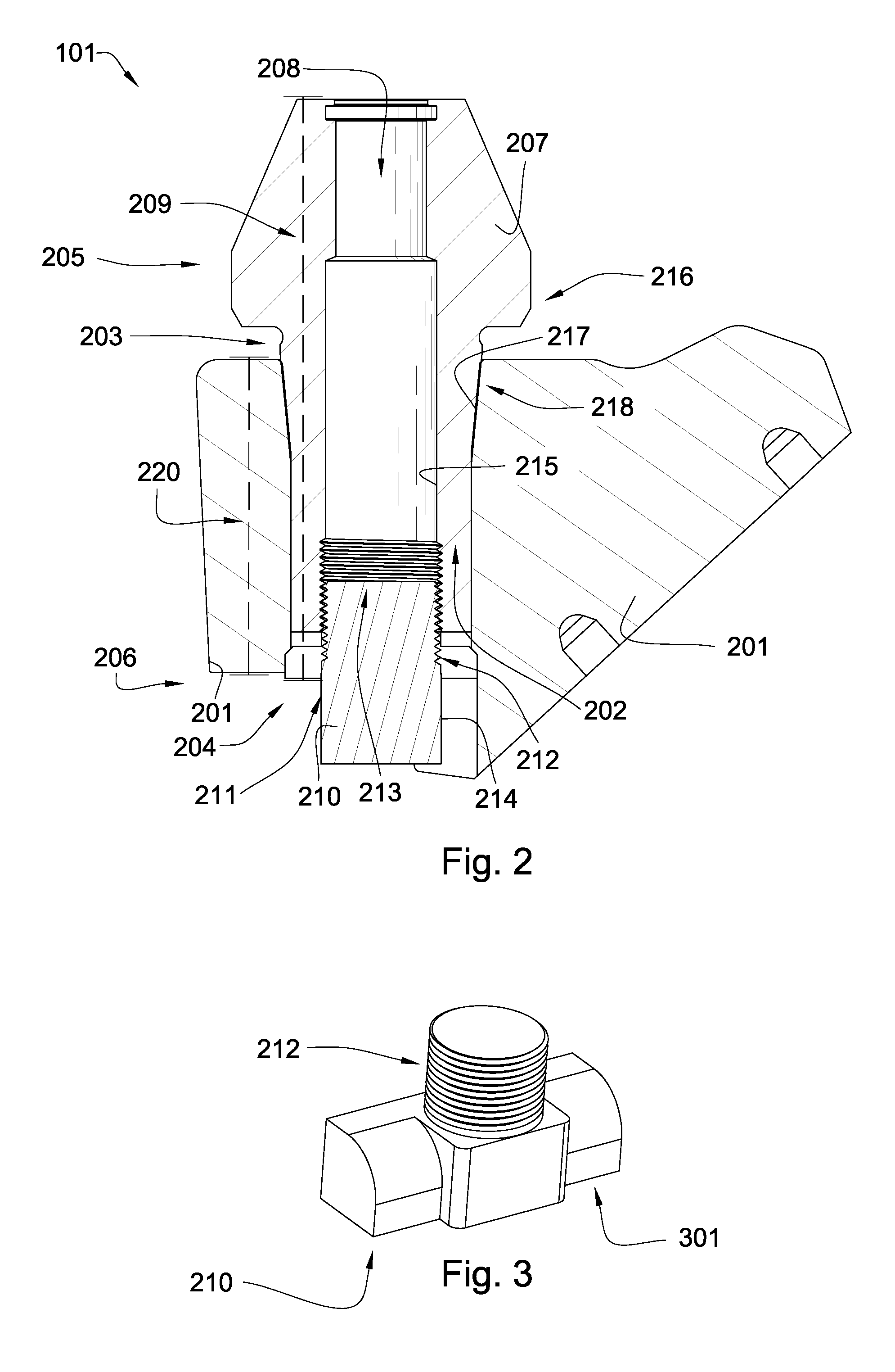
[0022]FIG....


PUM


Abstract

In one aspect of the invention, a holder assembly comprises a connection block having a block bore extending from a first opening proximate a first end of the assembly to a second opening proximate a second end of the assembly. The block is adapted for connection to a driving mechanism. An extension element is disposed in the block bore and protrudes from the first opening of the block bore. The extension element comprises a central extension bore having a longitudinal length. An attachment mechanism is disposed within the central extension bore of the extension element and is disposed proximate the second end of the assembly.

Description

CROSS REFERENCE TO RELATED APPLICATIONS [0001] This application is a continuation-in-part of U.S. patent application Ser. No. 11 / 947,644 filed on Nov. 29, 2007 which was a continuation-in-part of U.S. patent Ser. No. 11 / 844,586 filed on Aug. 24, 2007. U.S. patent application Ser. No. 11 / 844,586 is a continuation-in-part of U.S. patent application Ser. No. 11 / 829,761, which was filed on Jul. 27, 2007. U.S. patent application Ser. No. 11 / 829,761 is a continuation-in-part of U.S. patent application Ser. No. 11 / 773,271 which was filed on Jul. 3, 2007. U.S. patent application Ser. No. 11 / 773,271 is a continuation-in-part of U.S. patent application Ser. No. 11 / 766,903 filed on Jun. 22, 2007. U.S. patent application Ser. No. 11 / 766,903 is a continuation of U.S. patent application Ser. No. 11 / 766,865 filed on Jun. 22, 2007. U.S. patent application Ser. No. 11 / 766,865 is a continuation-in-part of U.S. patent application Ser. No. 11 / 742,304 which was filed on Apr. 30, 2007. U.S. patent applic...

Claims


Application Information

Patent Timeline
Patent Type & Authority Applications(United States)
IPC IPC(8): E21C25/10
CPCE21C35/183E21C35/19E21C2035/1826E21C2035/1806E21C35/1933E21C35/1831E21C35/188
Inventor HALL, DAVID R.JEPSON, JEFFWILDE, TYSON J.
Owner NOVATEK INC
Why Eureka
Try Eureka