
Spacecraft equipment pose information measuring method based on six-freedom-degree laser tracking target

A technology of laser tracking and measurement method, applied in measurement devices, measurement instruments, instruments, etc., can solve the problems of low measurement efficiency, difficult measurement, and many occupations, achieve high measurement accuracy, and reduce the occupation rate of measurement personnel and equipment. , Improve the effect of on-site measurement efficiency

Active Publication Date: 2018-03-09
BEIJING INST OF SPACECRAFT ENVIRONMENT ENG
View PDF6 Cites 18 Cited by
  • Summary
  • Abstract
  • Description
  • Claims
  • Application Information

AI Technical Summary

Problems solved by technology

[0005] In order to solve the above-mentioned technical problems, the object of the present invention is to provide a method for measuring the position and attitude of spacecraft equipment simply by measuring a single point of a target with a laser tracker or a total station, which solves the current problem of using multiple theodolites to collimate and interact with each other. Aiming at the problems of low measurement efficiency, high measurement difficulty and many personnel occupied in the measurement, on the basis of ensuring high angle measurement accuracy, the convenience, flexibility and measurement efficiency of the installation accuracy measurement of the spacecraft assembly site equipment are greatly improved, effectively Meet the needs of spacecraft development

Method used


Image

  • Spacecraft equipment pose information measuring method based on six-freedom-degree laser tracking target
  • Spacecraft equipment pose information measuring method based on six-freedom-degree laser tracking target
  • Spacecraft equipment pose information measuring method based on six-freedom-degree laser tracking target

Examples


Embodiment Construction

[0029] The present invention will be described in further detail below in conjunction with the accompanying drawings, but this is only exemplary and not intended to limit the protection scope of the present invention.

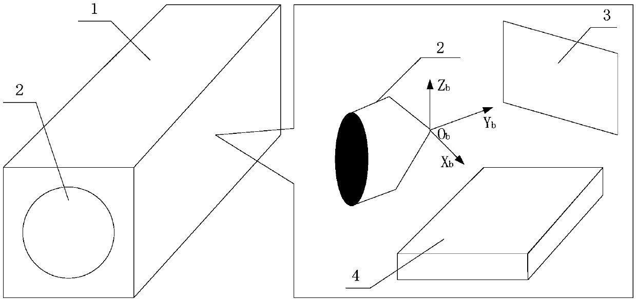
[0030] see image 3 , image 3Shows the schematic diagram of the composition of the six-degree-of-freedom laser tracking target in the method of the present invention; wherein, the six-degree-of-freedom laser tracking target in the method of the present invention: consists of a corner cube prism, an area array camera and a horizontal inclinometer, the angle of the corner cube prism There are small cuts at the cone. The measurement laser of the laser tracker or total station passes through the corner cube prism of the cooperative target for tracking and measurement, and most of the light is returned by the original path, which is no different from ordinary prism measurement, and the other part is received by the rear imaging system through the cutout. In this ...


PUM


Abstract

The invention discloses a spacecraft equipment pose information measuring method based on a six-freedom-degree laser tracking target. The method is characterized in that the six-freedom-degree laser tracking target and a laser tracker or total station are utilized, and by virtue of relative pose relation of each equipment laser tracking target coordinate system relative to the laser tracker or a total station coordinate system, the measurement of the relative pose relation among different equipment coordinate systems is realized by carrying out coordinate system transmission operation. The method disclosed by the invention can be used for solving the problems that measurement efficiency is low, measurement difficulty is big and many people are needed when multiple theodolites are utilizedfor realizing measurement through collimation and mutual alignment currently, convenience; the flexibility and measurement efficiency of spacecraft general assembly field equipment mounting accuracy measurement are greatly improved on the basis of guaranteeing relatively high angle measurement accuracy; and spacecraft development demands are effectively met.

Description

technical field [0001] The invention belongs to the technical field of industrial measurement, and specifically relates to a method for quickly measuring the relative pose relationship between spacecraft equipment by combining a six-degree-of-freedom laser tracking target and using a laser tracker or a total station to measure points, which can be applied to the following The cubic mirror is used as the coordinate system reference to quickly measure the pose relationship between devices. Background technique [0002] In the integrated manufacturing process of modern large-scale precision systems represented by spacecraft assembly, it is necessary to precisely measure the relative attitude angles between a large number of different devices. The benchmark of equipment that requires high-precision assembly usually uses an optical plane mirror or an optical cube mirror. The normal line of the cube mirror or plane mirror represents the coordinate axis direction of the equipment, ...

Claims


Application Information

Patent Timeline
Patent Type & Authority Applications(China)
IPC IPC(8): G01C15/00
CPCG01C15/00
Inventor 隆昌宇易旺民陶力阮国伟胡瑞钦孟凡伟孟少华陈畅宇贺文兴董悫
Owner BEIJING INST OF SPACECRAFT ENVIRONMENT ENG
Learn More