
Aiming Device For Billiard Cue

a cue and cue technology, applied in the field of cue aiming devices, can solve the problems of insufficient accuracy of cue striking, difficulty in adjusting the striking strength and direction of the cue, and difficulty in aiming at the ball precisely by naked eyes

Inactive Publication Date: 2008-04-17
LIU SEN YUNG
View PDF8 Cites 18 Cited by
  • Summary
  • Abstract
  • Description
  • Claims
  • Application Information

AI Technical Summary

Benefits of technology

[0008]According to the present invention, the parallel light source may be a laser light source or other light sources. The fixing member may be a fixing clamp or a clamp that is sleeved on the billiard cue and fastened with screws. There is no limitation to the structure of the fixing member as long as it can fix the aiming device with the billiard cue. The extending member may be, but not limited to, a curved rigid member. Any flexible or bendable extending members such as a flexible member in accordance with the present invention or a multiple rod linkage with ball pivot mechanisms are applicable, so as to be capable of adjusting a desired angle and a range of the projection light emitted from the parallel light source. The cylindrical lens may be a circular, biconvex, biconcave, plano-convex, or plano-concave cylindrical lens.
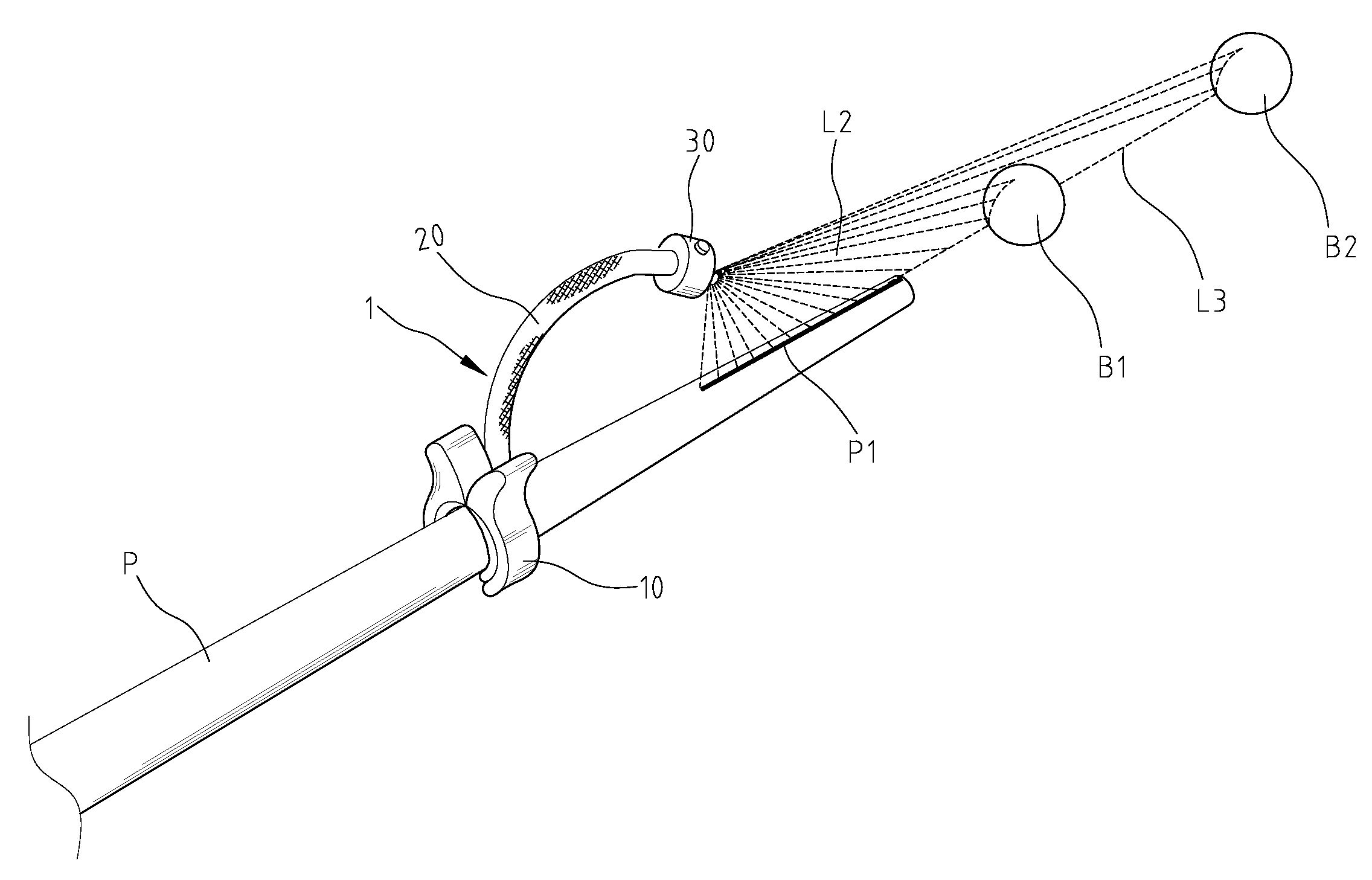
[0009]The parallel light beam can be refracted by the cylindrical lens to produce a fanned light beam. The fanned light beam is projected to form a projection line when it radiates on a surface of an object. Along the projection line, the billiard cue is in alignment with the cue ball and the object ball so that the cue ball can be hit to impact onto the object ball precisely. Travel trajectories of the cue ball and the object ball can be controlled through the help of the projection line.

Problems solved by technology

Due to the inaccuracy of the viewing angle and the difficulty of long-distance aiming, the way of aiming at the ball by naked eyes is not precise enough.
It can only help a little to adjust the striking strength and direction of the cue.
Hence, ordinary people except for those skilled billiard players are hard to aim at the ball precisely by naked eyes.
Later a laser light aiming device was produced, which could project a light point onto an object ball to be struck, but there is not a baseline between the projection point and the billiard cue, thereby players still cannot aim at the ball precisely.

Method used


Image

  • Aiming Device For Billiard Cue
  • Aiming Device For Billiard Cue
  • Aiming Device For Billiard Cue

Examples


Embodiment Construction

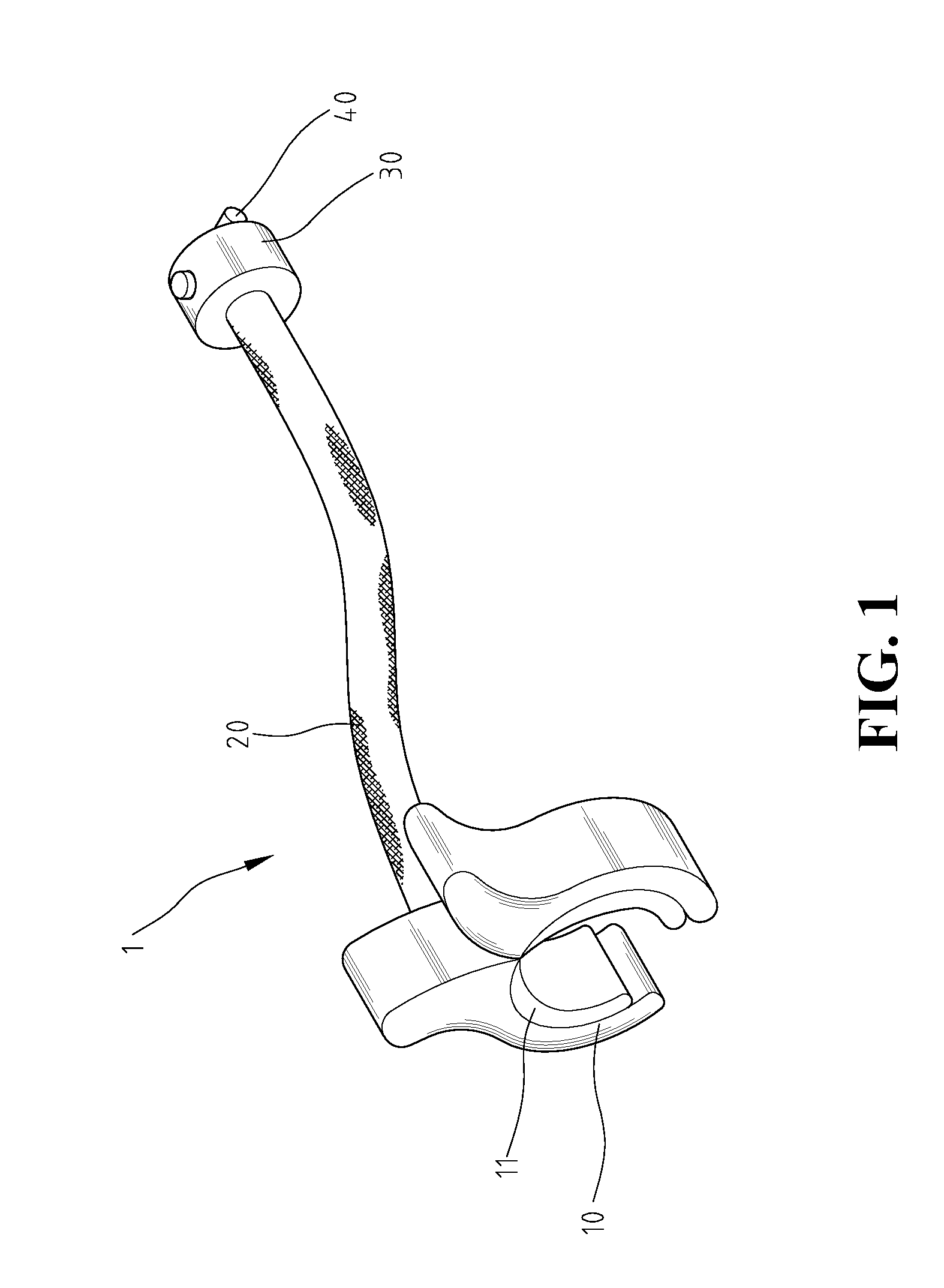
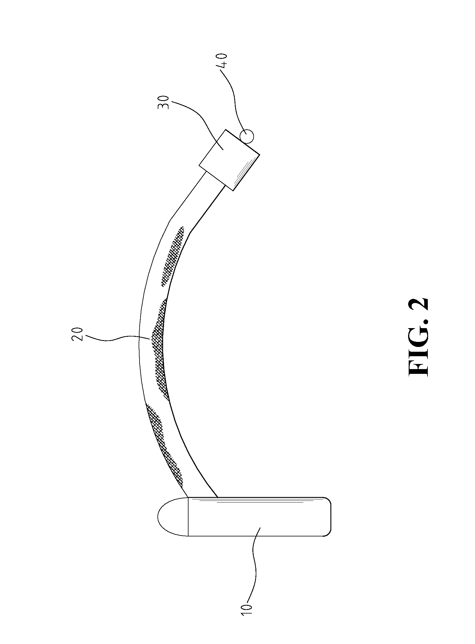
[0019]With reference to FIGS. 1 and 2, an aiming device 1 for a billiard cue in accordance with the present invention comprises a fixing member 10, an extending member 20, a parallel light source 30 and a cylindrical lens 40. The fixing member 10 is coupled with one end of the extending member 20 and the parallel light source 30 is coupled with the other end of the extending member 20. The cylindrical lens 40 is mounted on an end surface of the parallel light source 30, whereby a fanned light beam is projected out of the cylindrical lens 40 when a parallel light beam emitted from the parallel light source 30 passes through the cylindrical lens 40. The fanned light beam is projected on a surface of an object to form a projection line for aiming.

[0020]The fixing member 10 is, but not limited to, a fixing clamp in this embodiment. An inner rim of the fixing clamp 10 is configured to fit to an outer shape of a billiard cue P (see FIG. 6) for mounted thereon. A gasket 11 can be further d...


PUM


Abstract

An aiming device for a billiard cue is disclosed herein, which includes a fixing member, an extending member coupled with the fixing member at one end thereof, a parallel light source coupled with the other end of the extending member and having a projection hole for passing a parallel light beam emitted from the parallel light source, and a cylindrical lens mounted on one end of the parallel light source in front of the projection hole, whereby the parallel light beam becomes a fanned light beam after it passes through the cylindrical lens. The aiming device of the present invention can provide a high precise aiming in billiards.

Description

BACKGROUND OF THE INVENTION[0001]1. Field of the Invention[0002]The present invention relates to an aiming device for a billiard cue, and in particular to an aiming device that can provide a high precise aiming in billiards.[0003]2. The Prior Arts[0004]Generally, when striking a cue ball, people use naked eyes to aim at the ball. Due to the inaccuracy of the viewing angle and the difficulty of long-distance aiming, the way of aiming at the ball by naked eyes is not precise enough. It can only help a little to adjust the striking strength and direction of the cue. Hence, ordinary people except for those skilled billiard players are hard to aim at the ball precisely by naked eyes.[0005]Currently, aiming reference points are located at a periphery of a conventional billiard table. If these points are located at the other side of the table, it is inevitable to have a deviation of aiming by naked eyes. Later a laser light aiming device was produced, which could project a light point onto...

Claims


Application Information

Patent Timeline
IPC IPC(8): A63D15/00
CPCA63D15/006
Inventor LIU, SEN-YUNG
Owner LIU SEN YUNG
Learn More