
Manipulator

Inactive Publication Date: 2008-04-17
TERUMO KK +1
View PDF8 Cites 1019 Cited by
  • Summary
  • Abstract
  • Description
  • Claims
  • Application Information

AI Technical Summary

Benefits of technology

[0016]It is one of the objects of the present invention to provide a manipulator, which is capable of rolling a working unit with ease, while allowing a user to learn how to operate the manipulator within a short period of time during a training process.

Problems solved by technology

Therefore, cases that can be handled under usual endoscopic surgery training practices are limited to a certain range, and surgeons need to be highly trained and quite skilled in order to be able to perform endoscopic surgery in various other cases outside of the limited range.
However, it has been pointed out that surgical operations performed with a master-slave robot suffer from the following problems: 1. Since the slave manipulator constructed as a robotic arm needs to be positioned and fixed in advance, it takes time to prepare for surgery.
Since it is also necessary to position the robotic arm in advance for each surgical case, it is burdensome to draw up operation protocols, and such procedures are not applicable to certain surgical cases.
If unexpected trouble happens during the surgical operation, and the operation needs to be changed to a thoracotomy or a laparotomy, then since it is time-consuming to remove the robotic arm, the duration of the operation increases, resulting in a highly invasive situation for the patient.
The overall endoscopic surgical system is complex in structure, large in scale, and highly expensive to manufacture.
This is because the increased degree of freedom of the working unit results in an increased number of input members, which makes the working unit complex to operate, for example.
Further, it is time-consuming for the surgeon to confirm operation of the working unit in yawing and rolling directions, and also in positive and negative directions, so that the manipulator cannot be operated using easy techniques.
In particular, endoscopic surgery often requires fine manipulations in long hours.
However, if the input unit is slightly displaced from the neutral position, the operating unit undesiredly continues to move in one of opposite directions at a low speed.
Also, even if the input unit is maintained at the neutral position, when an unintentional slight touch on the input unit results in moving the operating unit, a user cannot operate it easily.
Stated otherwise, when response sensitivity of the manipulator is too high, the manipulator is not easy for the user to operate.

Method used


Image

  • Manipulator
  • Manipulator
  • Manipulator

Examples


Embodiment Construction

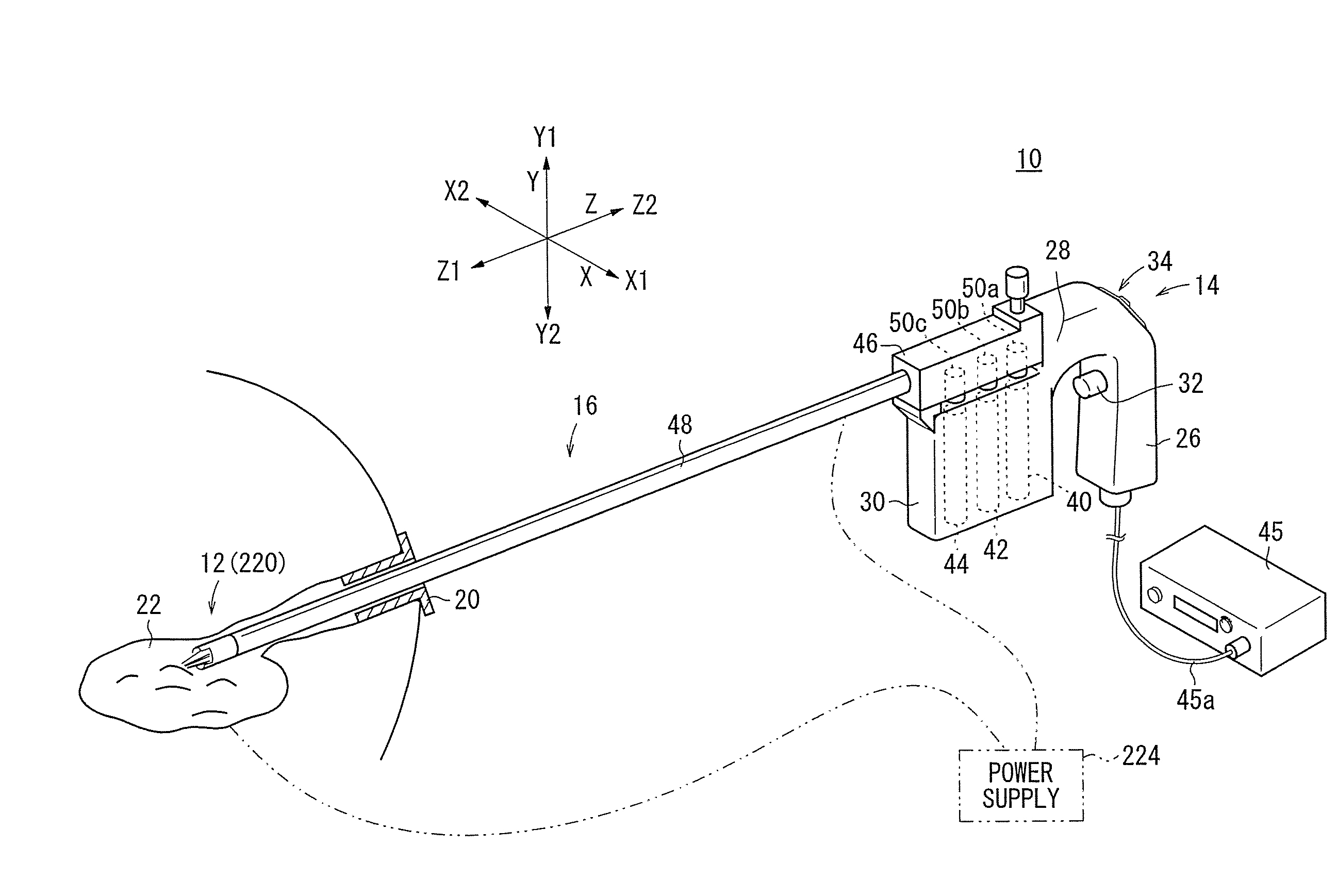
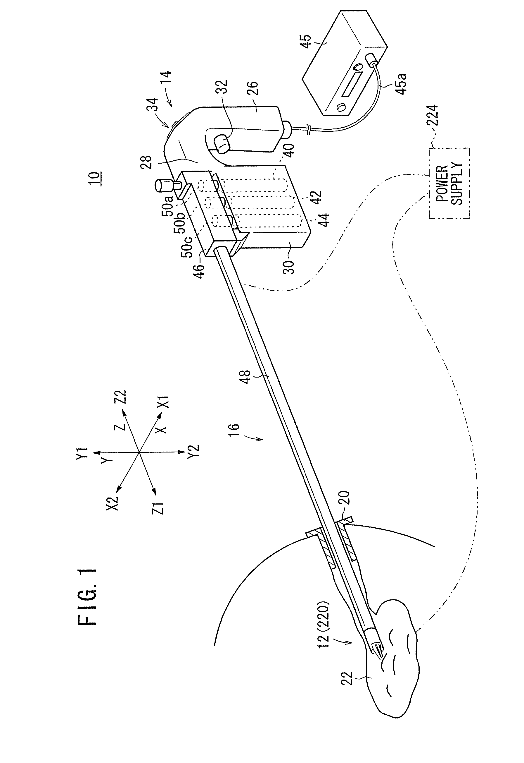
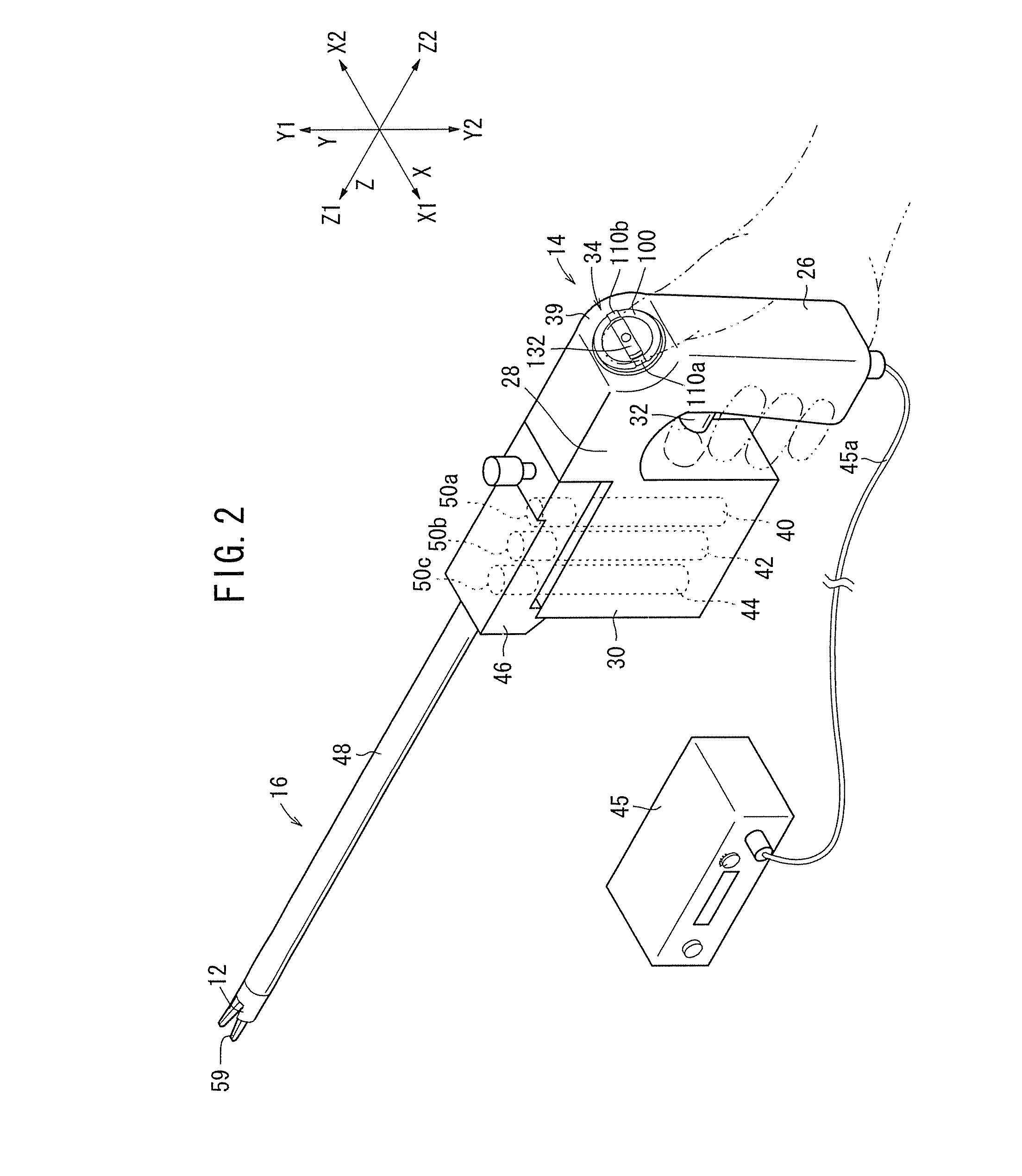
[0088]Manipulators according to preferred embodiments of the present invention shall be described below with reference to FIGS. 1 through 23. A manipulator 10 (see FIG. 1) according to an embodiment of the present invention comprises a medical manipulator for use in endoscopic surgical operations or the like.

[0089]As shown in FIG. 1, the manipulator 10 includes a working unit 12 on a tip end thereof, for gripping a portion of a living tissue, a curved needle, or the like. The manipulator 10 usually is referred to as a gripping forceps or a needle driver (needle holder).

[0090]As shown in FIGS. 1 and 2, the manipulator 10 comprises an operation command unit (operating unit) 14 on a proximal end thereof, which is held and operated by hand, a working unit 12 on a distal end thereof for working on a living tissue, and an elongate connector 16 interconnecting the working unit 12 and the operation command unit 14. The working unit 12 and the connector 16 have small diameters and can be ins...


PUM


Abstract

A manipulator includes an operation command unit to be gripped by a hand, a composite input unit operable by a finger, a connector shaft extending from the operation command unit, and a working unit disposed on a distal end of the connector shaft. The working unit includes a yawing mechanism, a rolling mechanism, and an opening and closing mechanism. The composite input unit has a shuttle ring for actuating the rolling mechanism, and a pad for actuating the yawing mechanism. The shuttle ring is an angularly movable member having two knobs disposed in respective left and right positions. The pad is disposed inside of the shuttle ring.

Description

[0001]This application claims the benefit of U.S. Provisional Application No. 60 / 855,382 filed on Oct. 31, 2006, U.S. Provisional Application No. 60 / 855,377 filed on Oct. 31, 2006 and U.S. Provisional Application No. 60 / 855,376 filed on Oct. 31, 2006.BACKGROUND OF THE INVENTION[0002]1. Field of the Invention[0003]The present invention relates to a manipulator having a hand-gripped operating unit, a connector extending from the operating unit, and a working unit angularly movable when the operating unit is operated.[0004]2. Description of the Related Art[0005]In endoscopic surgery (also called laparoscopic surgery), it is customary to form a plurality of incisions in the body surface of the patient, insert trocars (tubular instruments) into the respective incisions as forceps instrument passage ports, and to introduce the tip ends of forceps instruments having shafts through the respective trocars into a body cavity, to perform a surgical operation on an affected part of the body. Wo...

Claims


Application Information

Patent Timeline
IPC IPC(8): A61B1/012
CPCA61B17/062A61B17/29A61B17/2909A61B19/22A61B2017/00199A61B2017/00367A61B2019/2292A61B2017/2925A61B2017/2929A61B2017/2939A61B2019/2242A61B2019/2269A61B2019/2276A61B2017/00424A61B2034/742A61B34/70A61B34/71A61B34/74A61B34/76
Inventor OMORI, SHIGERUUENOHARA, SHUICHIJINNO, MAKOTOSUNAOSHI, TAKAMITSU
Owner TERUMO KK
Learn More