File transfer server

a file transfer and server technology, applied in the field of file transfer servers, can solve the problems of various problems, problems in terms of security, terms of practical use, etc., and achieve the effect of safe and practicable sharing of files

Active Publication Date: 2008-04-17
MURATA MASCH LTD
View PDF76 Cites 11 Cited by
  • Summary
  • Abstract
  • Description
  • Claims
  • Application Information

AI Technical Summary

Benefits of technology

[0012]In order to solve the problems described above, preferred embodiments of the present invention provide a mechanism to safely and practically share a file via a wide area network such as the Internet, and provide a mechanism for dynamic shared use

Problems solved by technology

However, various problems must be solved in order to safely share the file between the different LANs via the Internet.
That is, there arise many problems in terms of security when information about a shared file is referred to as it is over the Internet.
In addition, there arise problems in terms of practical use because a LAN has no mechanism to dynamically send information about a shared file to another LAN.
However, if a file is newly added or the file to be shared is deleted

Method used


Image

  • File transfer server
  • File transfer server
  • File transfer server

Examples


first preferred embodiment

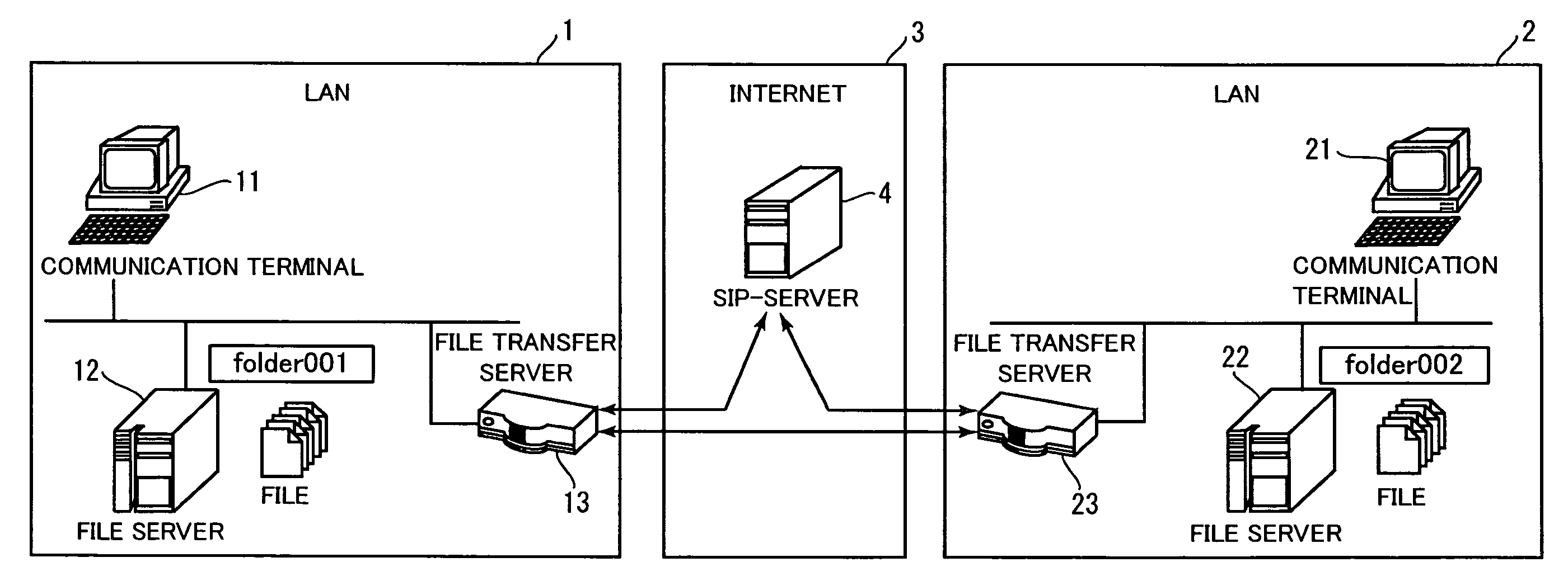
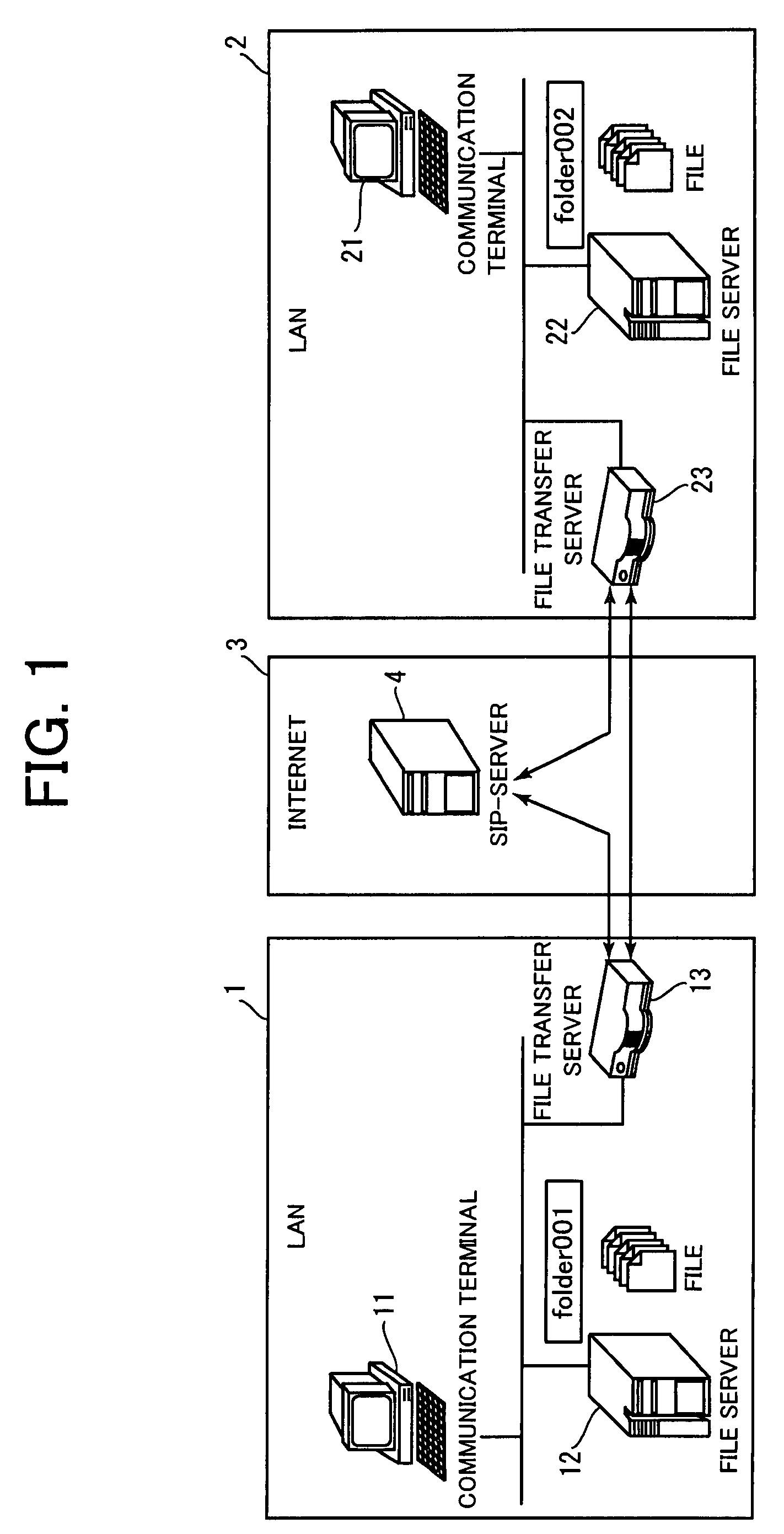
[0037]Hereinafter, description will be given of a first preferred embodiment of the present invention with reference to the drawings. FIG. 1 illustrates a general configuration of a communication system according to the first preferred embodiment. The communication system preferably includes the Internet 3 and two local area networks (LANs) 1, 2 each connected to the Internet 3. The LANs 1 and 2 are located at physically remote places, respectively. For example, the LAN 1 corresponds to a local network located at a head-office building, and the LAN 2 corresponds to a local network located at a branch-office building. Each of the LANs 1 and 2 is connected to the Internet 3 which is a global network.

[0038]As illustrated in FIG. 1, a communication terminal 11 and a file server 12 are connected to the LAN 1. Each of the communication terminal 11 and the file server 12 has a private IP address. As described above, typically, a terminal connected to a LAN has a private IP address which is...

second preferred embodiment

[0080]Hereinafter, description will be given of a second preferred embodiment of the present invention with reference to the drawings. FIG. 6 illustrates a general configuration of a communication system according to the second preferred embodiment. The communication system preferably includes the Internet 1003 and three LANs 1001, 1002, 1005 each connected to the Internet 1003. The LANs 1001, 1002 and 1005 are preferably located at physically remote places, respectively. For example, the LAN 1001 corresponds to a local network located at a head-office building, and each of the LANs 1002 and 1005 corresponds to a local network located at a branch-office building. Each of the LANs 1001, 1002 and 1005 is connected to the Internet 1003 which is a global network.

[0081]As illustrated in FIG. 6, a communication terminal 1011 and a file server 1012 are connected to the LAN 1001. Each of the communication terminal 1011 and the file server 1012 has a private IP address. As described above, t...


PUM


Abstract

A technique allows shared use of a file between different networks via the Internet. File transfer servers on different LANs access file servers on the respective LANs to prepare a list of shared files, respectively. The file transfer servers are registered in a SIP server, and then send a SUBSCRIBE method to each other to issue a request to transfer the file list, respectively. In response to the request, the file lists are exchanged. A communication terminal on each LAN makes a request to acquire a specific file on the basis of information about the shared files stored in the file transfer server. Through a media session, one of the file transfer servers issues a request to acquire the file to the other file transfer server. As a result, the file is transferred to the communication terminal.

Description

CROSS-REFERENCE TO RELATED APPLICATIONS[0001]This application claims priority under 35 U.S.C 119 to Japanese Patent Application No. 2006-277246, filed on Oct. 11, 2006, and No. 2006-277372, filed on Oct. 11, 2006, which applications are hereby incorporated by reference in their entirety.BACKGROUND OF THE INVENTION[0002]1. Field of the Invention[0003]The present invention relates to a technique of accessing files in different networks.[0004]2. Description of Related Art[0005]Use of a call control protocol such as a SIP (Session Initiation Protocol) or a DDNS (Dynamic Domain Name System) allows communication terminals on different LANs (Local Area Networks) to directly carry out communications with each other via a WAN (Wide Area Network). Such a technique is referred to as a so-called VPN (Virtual Private Network). According to this technique, remote LANs can be used as if an interconnection is effected therebetween.[0006]For example, use of the technique effects a connection between...

Claims


Application Information

Patent Timeline
IPC IPC(8): G06F15/16
CPCG06F17/30094H04L67/147H04L67/14H04L67/06G06F16/134
Inventor TANIMOTO, YOSHIFUMI
Owner MURATA MASCH LTD
Why Eureka
Try Eureka