
Distributed pce-based system and architecture in multi-layer network

a multi-layer network and distributed path technology, applied in the field of telecoms, can solve problems such as complex path computation

Inactive Publication Date: 2008-04-17
FUTUREWEI TECH INC
View PDF16 Cites 15 Cited by
  • Summary
  • Abstract
  • Description
  • Claims
  • Application Information

AI Technical Summary

Benefits of technology

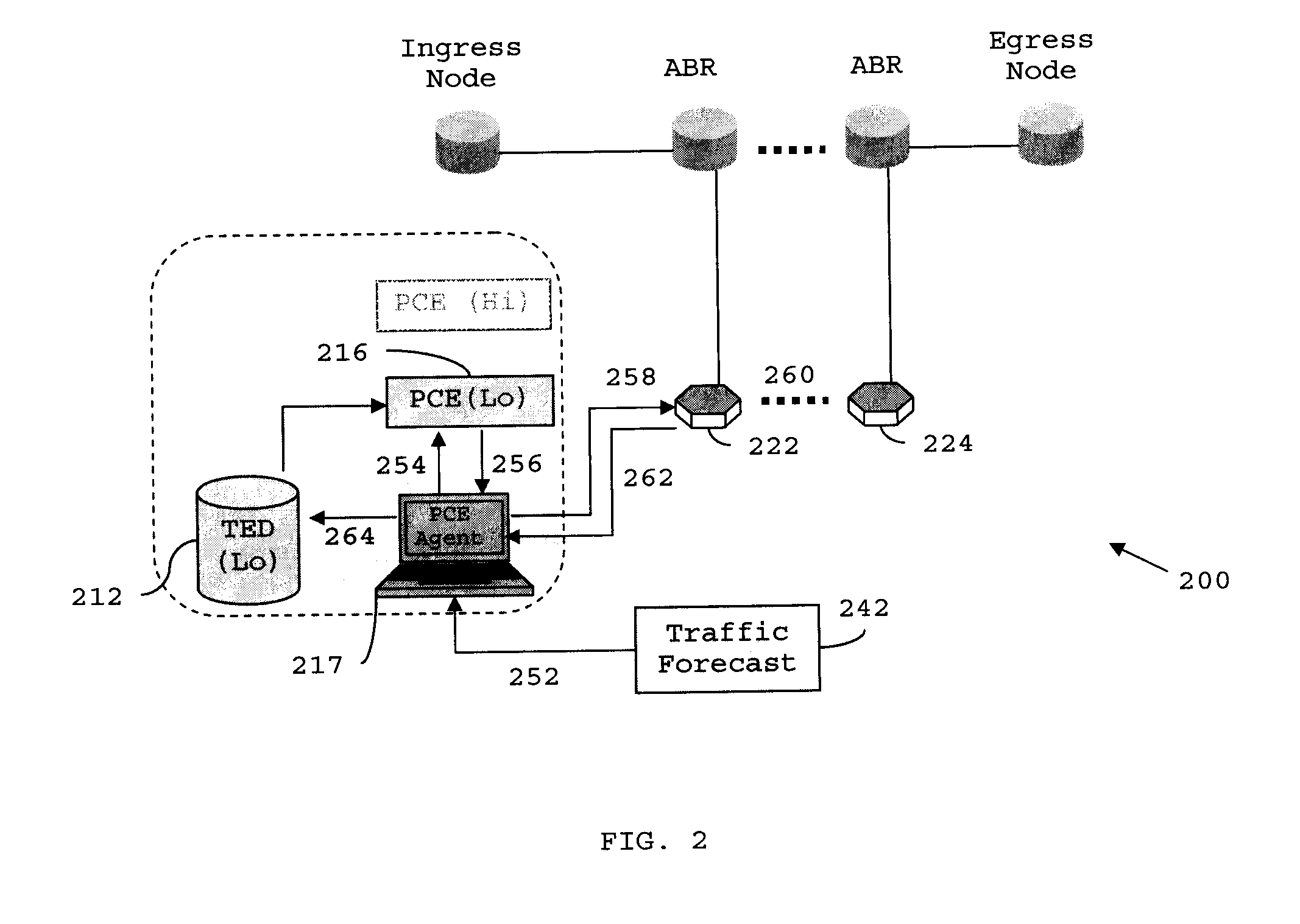
[0011]The present invention provides a static optical layer path provisioning mode, to establish optical LSPs on a pre-establishment basis. In addition, the present invention provides a dynamic multi-layer path provisioning mode, to dynamically establish an LSP, with cooperation between higher-layer and lower-layer PCEs.
[0012]The present invention further provides a crankback hold-off mechanism, to establish a dynamic light path upon detection of a crankback condition in an optical transport layer LSP.

Problems solved by technology

However, in these kind of networks, path computation is complex, and may require special computational components and cooperation between different network domains.

Method used


Image

  • Distributed pce-based system and architecture in multi-layer network
  • Distributed pce-based system and architecture in multi-layer network
  • Distributed pce-based system and architecture in multi-layer network

Examples


Embodiment Construction

[0019]The following discussion is presented to enable a person skilled in the art to make and use the invention. The general principles described herein may be applied to embodiments and applications other than those detailed below without departing from the spirit and scope of the present invention as defined herein. The present invention is not intended to be limited to the embodiments shown, but is to be accorded the widest scope consistent with the principles and features disclosed herein.

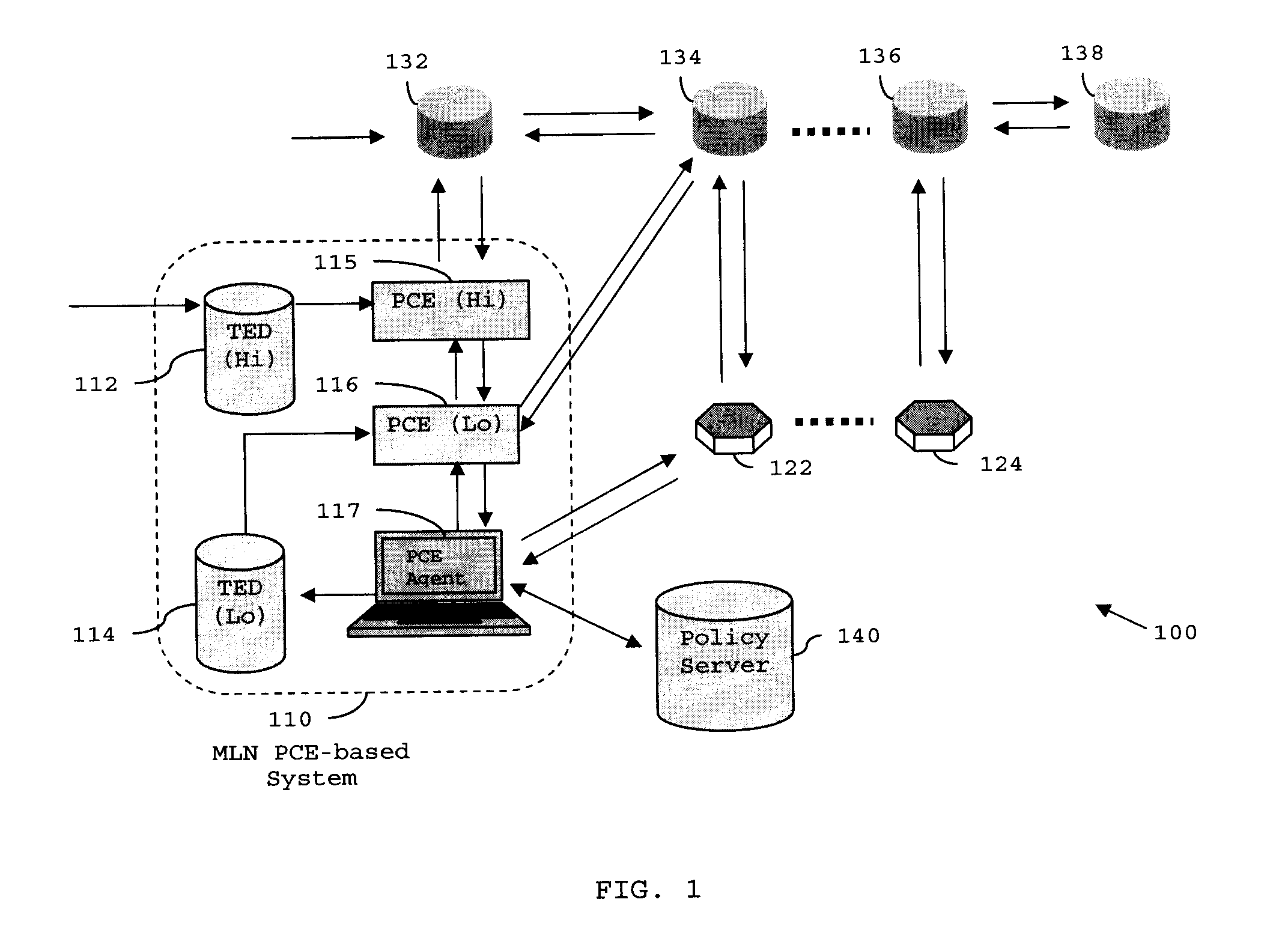
[0020]Referring now to drawings, and initially to FIG. 1, an embodiment of a distributed Path Computation Element based (PCE-based) multi-layer network architecture (100) is illustrated according to the present invention. The Multi-Layer Network (MLN) PCE-based system (110) may be taken as an independent server (i.e., an external entity) from the perspective of other network nodes.

[0021]MLN PCE-based system (110) includes a PCE (Hi) (115) and a PCE (Lo) (116), distributed in a higher-layer and ...


PUM


Abstract

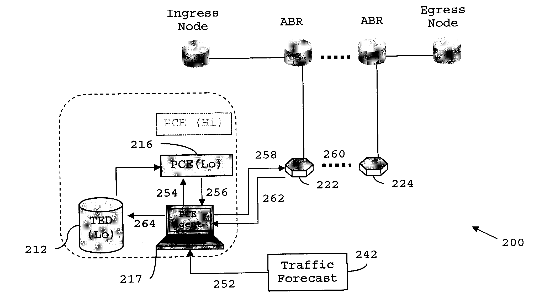
A distributed path computation element based system in a multi-layer network. The system comprises at least one higher-layer path computation element, and at least one lower-layer path computation element, adapted to provide dynamic multi-layer path computations; at least one higher-layer traffic engineering database, and at least one lower-layer traffic engineering database, adapted to provide multi-layer traffic engineering label switched paths, while maintaining layer-specific traffic engineered database in a distributed fashion; and at least one path computation element agent, adapted to provide static optical layer path provisioning, and reconfiguration of optical layer label switched paths in cooperation with the at least one lower-layer path computation element.

Description

CROSS-REFERENCE TO RELATED APPLICATIONS[0001]This application is related to: U.S. application Ser. No. ______, filed concurrently with the present invention on Oct. 16, 2006, entitled “SYSTEM OF PATH COMPUTATION ELEMENT PROTOCOL SUPPORT FOR LARGE-SCALE CONCURRENT PATH COMPUTATIONS”, by Young Lee.TECHNICAL FIELD OF THE INVENTION[0002]The present invention relates generally to telecommunications, and more particularly, to a distributed Path Computation Element based (PCE-based) system and architecture in a multi-layer network.BACKGROUND OF THE INVENTION[0003]A Path Computation Element (PCE) is an entity that is capable of computing a network path or route based on a network topology, and applying computational constraints to the computation. The capability of a PCE to compute different types of paths allows a PCE to provide traffic engineering functions.[0004]Constraint-based path computation is a fundamental building block for traffic engineering networks. However, in these kind of n...

Claims


Application Information

Patent Timeline
Patent Type & Authority Applications(United States)
IPC IPC(8): G06F15/173
CPCH04L45/00H04L45/308H04L45/44H04L47/825H04L47/10H04L47/125H04L45/50
Inventor LEE, YOUNG
Owner FUTUREWEI TECH INC
Learn More