
Tube Insert and Bi-Flow Arrangement for a Header of a Heat Pump

a heat pump and header technology, applied in the field of heat exchangers, can solve the problems of reducing the heat exchange efficiency of the heat exchanger, affecting the cooling capacity and efficiency of the air conditioner, and increasing the cost, so as to achieve the effect of extending the header substantially and more uniform

Active Publication Date: 2008-04-24
CARRIER CORP
View PDF51 Cites 62 Cited by
  • Summary
  • Abstract
  • Description
  • Claims
  • Application Information

AI Technical Summary

Benefits of technology

[0006] In accordance with one aspect of the invention, the distribution of two-phase refrigerant to the multiple channels of a microchannel heat exchanger in a heat pump can be made more uniform when operating in the cooling mode by the placement of a perforated tube within the inlet header, with the tube being fed refrigerant at its one end and extending substantially the length of the header. The perforations act as distributors to conduct the flow of two-phase refrigerant from the insert tube into the inlet manifold. In this manner, each region of the inlet header will be fed a well-mixed, uniform flow of two-phase refrigerant that then enters the individual channels in a uniform manner. A bi-flow expansion device is provided at the inlet to the perforated tube insert such that during cooling mode operation the refrigerate expansion occurs immediately before entering the perforated tube and during heating mode operation, the expansion device allows the refrigerant to bypass the perforated tube such that the refrigerant flows directly from the manifold to the expansion device.

Problems solved by technology

Since this two-phase refrigerant is a mixture of vapor and liquid, it tends to separate in the inlet header leading to maldistribution within the evaporator (i.e. some tubes are fed mostly vapor instead of a balanced mixture of vapor and liquid), which has a negative effect on the cooling capacity and efficiency of the air conditioner.
Because the performance is compromised in this manner, additional surface must be added to the evaporator to match the capacity and efficiency of a comparable round tube, plate fin evaporator.
This increases the cost as well.
Such a direct feed approach causes two-phase refrigerant to flow through the entire length of the header, with the vapor and liquid tending to separate out such that some tubes get mostly vapor and others get mostly liquid, thereby resulting in dry surfaces and poor utilization of the heat exchanger.
This method results in considerable additional expense over the direct feed method as additional hardware such as the distributor / feeder tube assembly must be added as well as the baffles in the header.
When particular structures are added to heat exchangers in order to promote uniform flow from the inlet manifold to the microchannels during cooling mode operation, those same structures may interfere with refrigerant flowing in the opposite direction during operation in the heating mode.

Method used


Image

  • Tube Insert and Bi-Flow Arrangement for a Header of a Heat Pump
  • Tube Insert and Bi-Flow Arrangement for a Header of a Heat Pump
  • Tube Insert and Bi-Flow Arrangement for a Header of a Heat Pump

Examples


Embodiment Construction

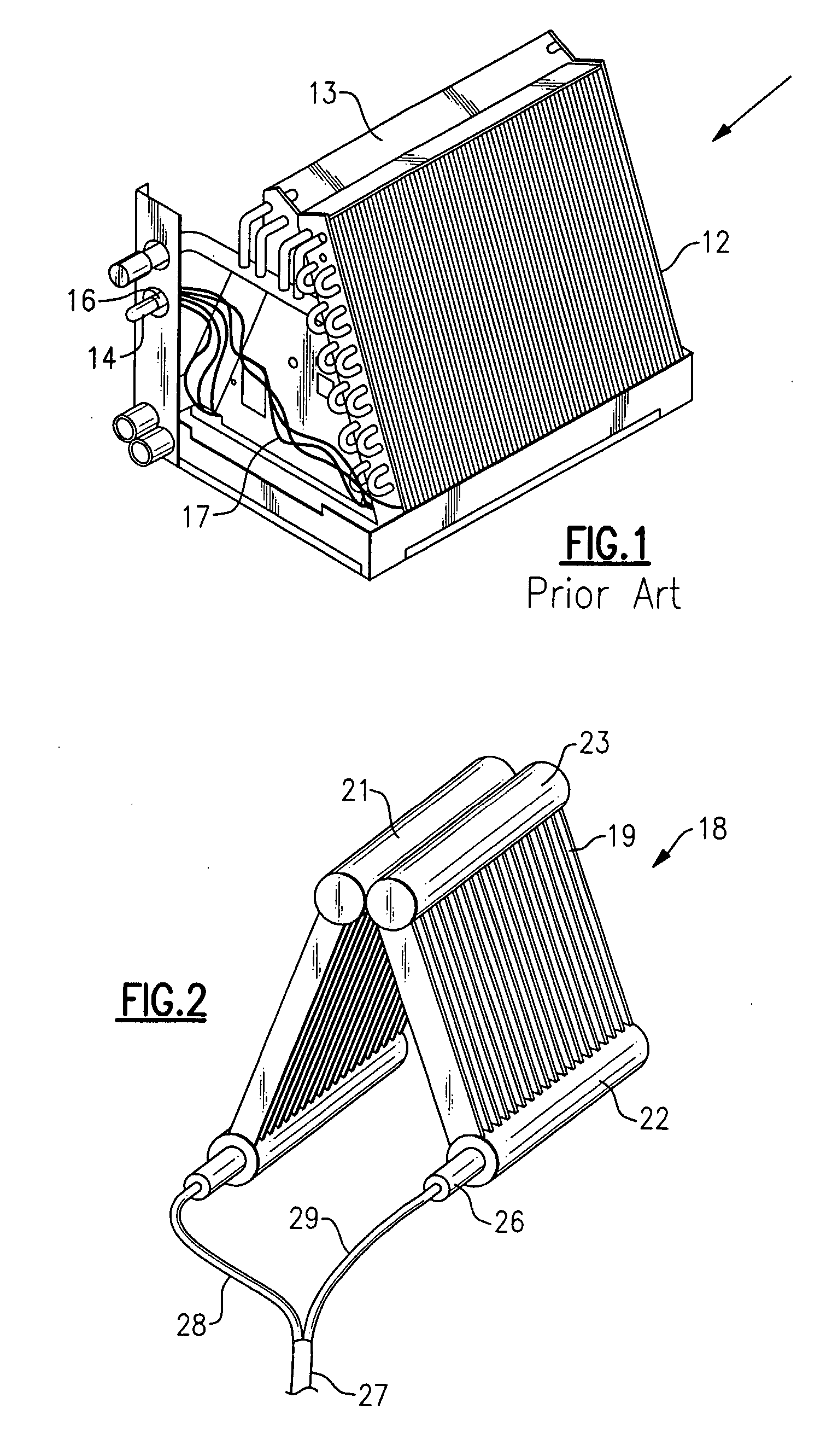
[0017] Referring to FIG. 1, there is shown a conventional A-coil having a pair of coil slabs 12 and 13 with each having a plurality of refrigerant carrying tubes passing through a plurality of fins which, in turn, are adapted to have air passed therethrough by way of a blower or fan.

[0018] In practice, liquid refrigerant from a condenser (not shown) passes to an expansion device 14, with the resulting two-phase refrigerant then passing to a distributor 16 and then to a plurality of connecting lines 17 that carry the two-phase refrigerant into the various circuits of tubes. As the air passes through the slabs 12 and 13 is cooled, the refrigerant is boiled off with the refrigerant vapor then passing to a compressor and then back to the condenser.

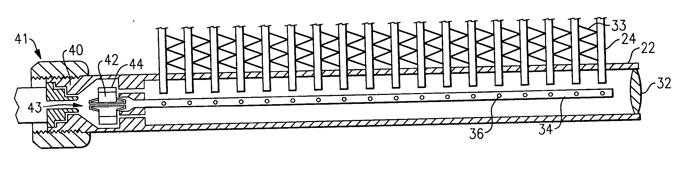
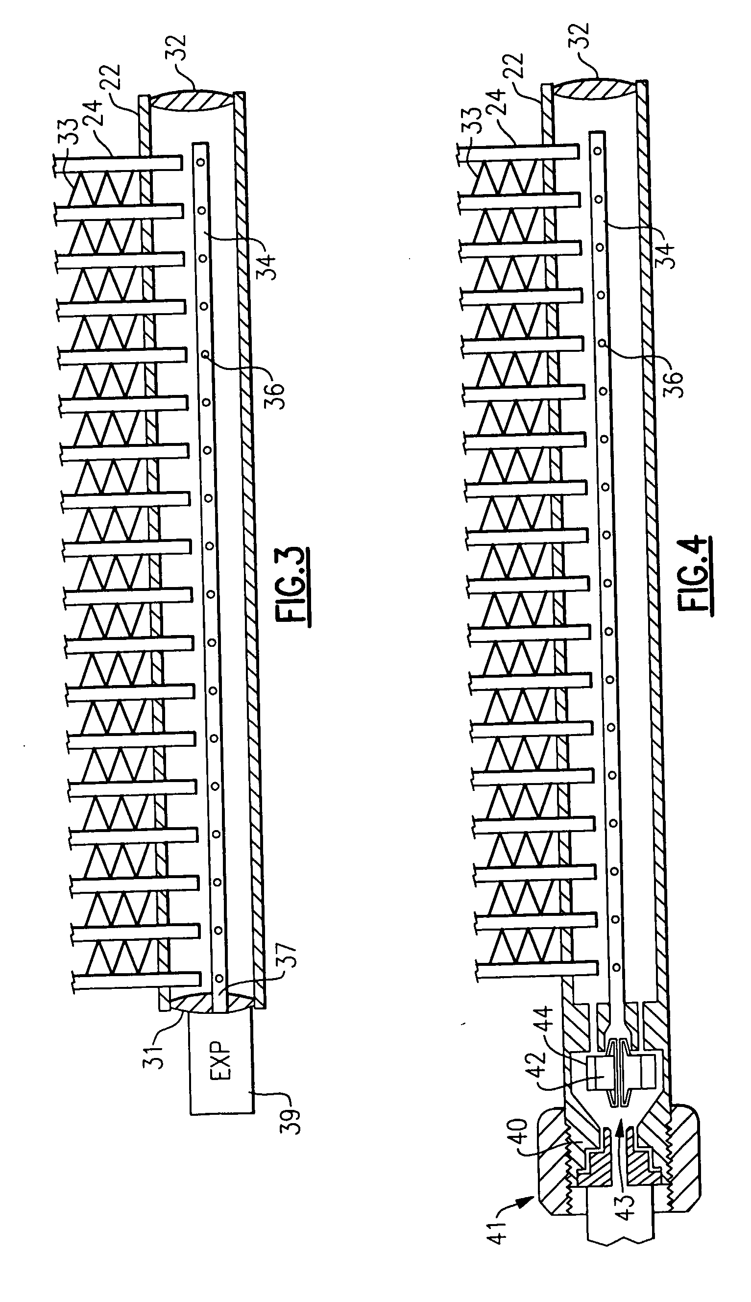
[0019]FIG. 2 shows a microchannel A-coil 18 in accordance with one aspect of the invention, with the A-coil 18 being formed of a pair of microchannel evaporator coils 19 and 21. Each of the microchannel evaporator coils 19 and 21 have an inl...


PUM

PropertyMeasurementUnit
Lengthaaaaaaaaaa
Sizeaaaaaaaaaa

Abstract

An inlet header (22) of a microchannel heat pump heat exchanger has a tube (34) disposed therein and extending substantially the length of the inlet header (22), with the tube (34) having a plurality of openings (36) therein. During cooling mode operation, refrigerant is caused to flow into an open end of the tube (34) and along its length to thereby flow from the plurality of openings (36) into the inlet header (22) prior to entering the microchannels (24) to thereby provide a uniform flow of two-phase refrigerant thereto. A bi-flow expansion device (41) placed at the inlet end of the tube (34) allows for the expansion of liquid refrigerant into the tube (34) during periods in which the heat exchanger operates as an evaporator and allows the refrigerant to flow directly from the header (22) and around the tube (34) during periods in which the heat exchanger operates as a condenser coil.

Description

TECHNICAL FIELD [0001] This invention relates generally to heat exchangers and, more particularly, to microchannel heat exchangers for use with two-phase refrigerant in a heat pump. BACKGROUND OF THE INVENTION [0002] Microchannel heat exchangers are currently designed in a parallel flow configuration, wherein there is a long inlet header that extends the length of the core and feeds multiple parallel tubes that then feed into an outlet header. The diameter of the headers must be larger than the major axis of the microchannel tube. When this parallel flow microchannel heat exchanger operates as an evaporator, two-phase refrigerant is being fed into the inlet header. Since this two-phase refrigerant is a mixture of vapor and liquid, it tends to separate in the inlet header leading to maldistribution within the evaporator (i.e. some tubes are fed mostly vapor instead of a balanced mixture of vapor and liquid), which has a negative effect on the cooling capacity and efficiency of the ai...

Claims


Application Information

Patent Timeline
IPC IPC(8): F25B29/00F28F27/02F28F9/02
CPCF25B39/028F25B41/067F25B2341/061Y10T29/49359F28D1/05366F28F9/0273F28F2260/02F25B2500/01F28F27/02F25B41/38F25B29/00F28F9/02
Inventor RIOS, ARTUROKIRKWOOD, ALLEN
Owner CARRIER CORP
Features
  • Generate Ideas
  • Intellectual Property
  • Life Sciences
  • Materials
  • Tech Scout
  • Unparalleled Data Quality
  • Higher Quality Content
  • 60% Fewer Hallucinations
Learn More