
Backlight Modulation For Display

a backlight modulation and display technology, applied in the field of displays, can solve the problems of difficult to retain a sufficient number of grey scale values after gamma correction, difficult to have sufficient detail in the darker video levels, and the native luminance curve of the crt display is strongly different from the traditional gamma curve of the display, so as to reduce flicker, facilitate the rise or fall time specification, and speed up the frame rate

Inactive Publication Date: 2008-04-24
BARCO NV
View PDF8 Cites 147 Cited by
  • Summary
  • Abstract
  • Description
  • Claims
  • Application Information

AI Technical Summary

Benefits of technology

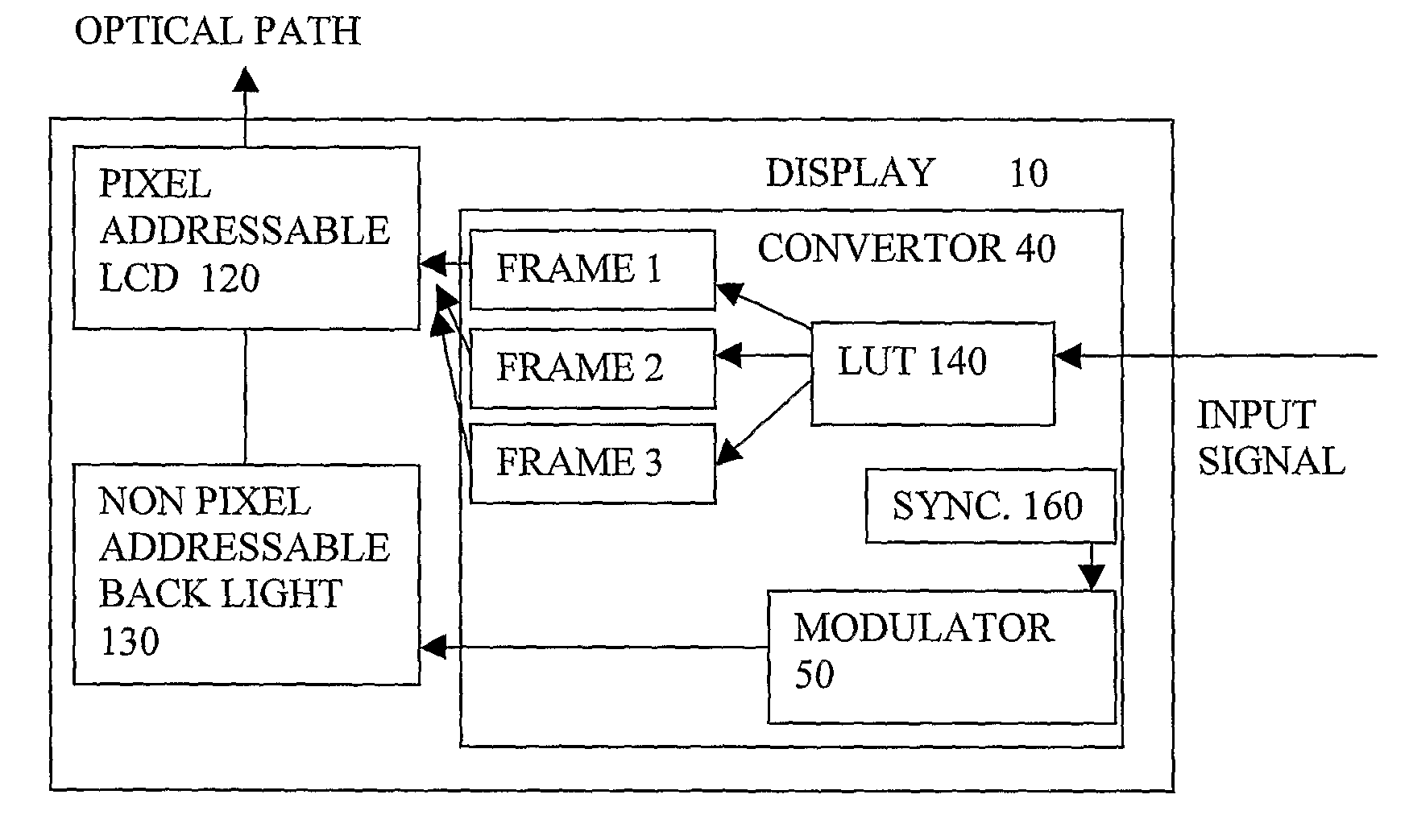
[0018] By the averaging of a sequence of different combinations, the apparent luminance or colour of the pixels can be made to take intermediate values between the gradations dictated by the stepsize corresponding to a least significant bit of the control provided by the pixel addressable part. In other words the amount of apparent quantization can be increased in a selected part of the range. This can enable more accurate reproduction of both colour and greyscale images, or corrections can be made to non-linearities in the display output. The above technique can be used in combination with an amount of conventional spatial or temporal dither. In particular, for a given accuracy, the present invention can enable an amount of conventional spatial or temporal dither to be reduced, and so the abovementioned disadvantages of the conventional dithers can be reduced. In principle, the modulation of the backlight or non-pixel addressable part can be in phase or out of phase with, and need not be at the same frequency as, changes in optical values for pixels of the pixel addressable part. In principle either or both of the non-pixel and pixel parts can have an active light source or have a passive light modulator, such as a reflective or transmissive part, in any combination of passive and active parts. If both parts are passive, another light source can be used.
[0020] An additional feature for a dependent claim is the backlight or non-pixel addressable part comprising a controllable light source, and the pixel addressable part comprising a reflective or transmissive layer. This can provide an additional advantage that at lower illumination levels, a grayscale stepsize is reduced, while at higher illumination levels, a stepsize is larger. Hence the additional intermediate output levels are concentrated at low illumination levels. This is where they are needed most, as explained above. Thus there are fewer wasted intermediate levels at higher illumination levels.
[0026] Another such feature is the values of the temporal sequence being chosen to remain within a limit on transition rate. This can help ease the rise or fall time specification for the pixel addressable part, or can enable a faster frame rate, to reduce flicker for example.
[0027] Another such feature is the modulation or the temporal sequence being scrambled. This can also help reduce flicker, particularly for longer modulation cycle times. This can encompass scrambling to change the sequence, or to increase frequency of peaks and troughs for example.
[0031] Another aspect of the invention provides a convertor for converting an input signal for a display into a first signal for temporal modulation of a backlight or non-pixel addressable part in an optical path of the display, and a second signal for controlling a pixel addressable part in the optical path of the display, the second signal comprising signals for providing a native set of optical values for each pixel of the display, the second signal also having a temporal sequence of output values for each pixel of the display, such that different optical values of the temporal sequence will coincide with different output levels of the modulated backlight or non-pixel addressable part to thereby provide intermediate optical values of the set by a combination of the optical outputs of the two parts averaged over a duration of the temporal sequence. The native set of optical values comprises more than two optical values, preferably 8 or more optical values, still more preferred more than 20 and even more than 100 optical values. The convertor may furthermore be adapted to convert the input signal so that the first signal is for modulating a colour point of the output of the backlight or non-pixel addressable part. This can help to compensate for shifts in colour point with luminance, for example.

Problems solved by technology

At present, most matrix based display technologies are technologically immature compared to long established electronic image forming technologies such as Cathode Ray Tubes (CRT).
As a result, some image quality deficiencies exist and cause problems for the acceptance of these technologies in certain applications, as will now be explained.
A first disadvantage of current matrix displays, such as but not limited to LCD displays and DMD / DLP (Digital Micromirror Devices / Digital Light Processing: pixels are formed by very small controllable mirrors that can be electronically set to one of two positions: one position reflects light onto the display screen and another position makes sure that the light is absorbed.
A disadvantage of such projection displays is that typically their native luminance curve strongly differs from the traditional gamma curve of the CRT displays.
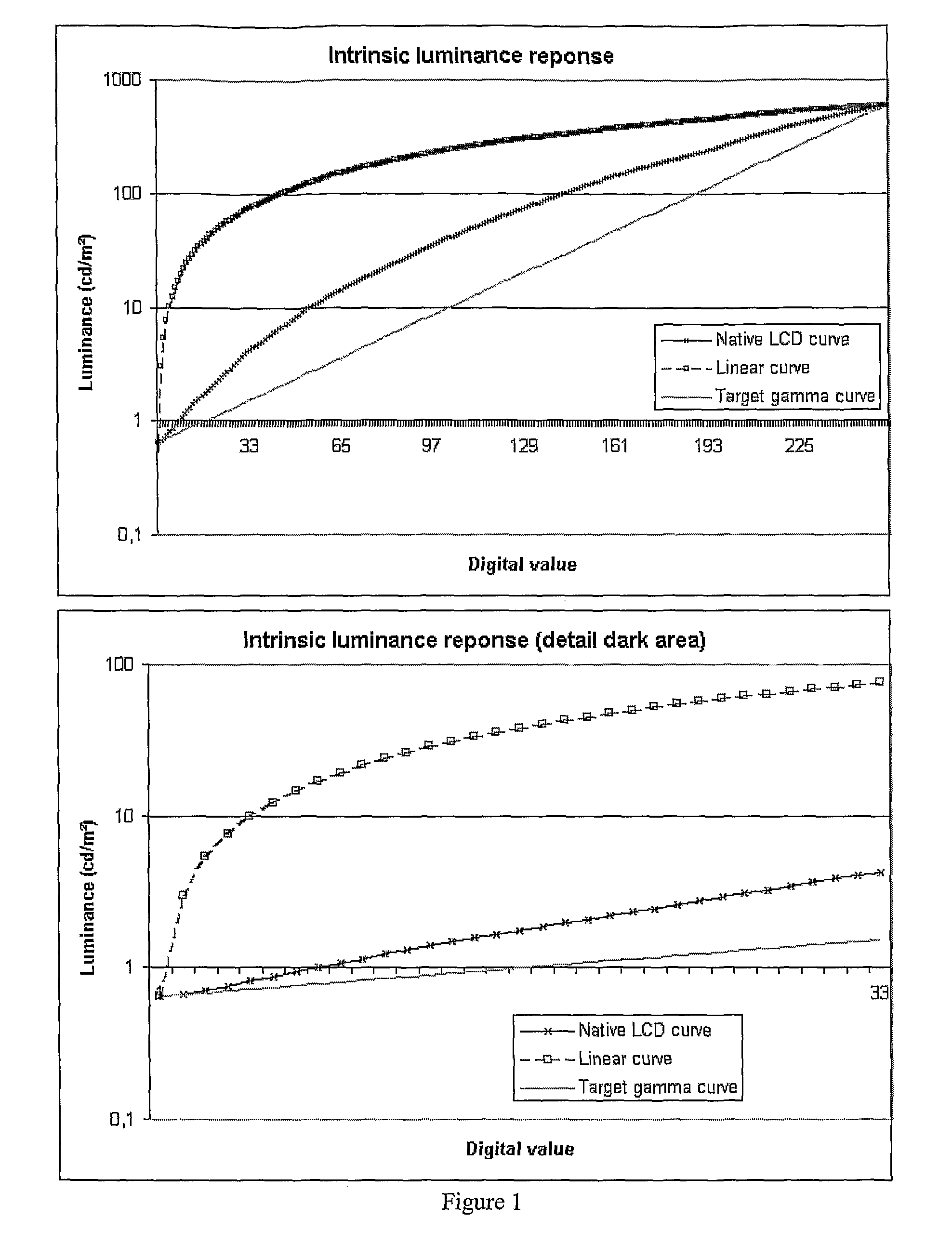
With current matrix displays the native curve often differs very much from the target luminance curve making it very difficult to retain a sufficient number of grey scale values after the gamma correction.
For example, with present LCD displays it is very difficult to have sufficient detail in the darker video levels because the native curve of the LCD differs a lot from the traditional gamma curve at darker video levels.
In case of a linear native curve (such as a DLP / DMD projector) the situation is even worse.
The disadvantage here is that the effective resolution of the display system is reduced.
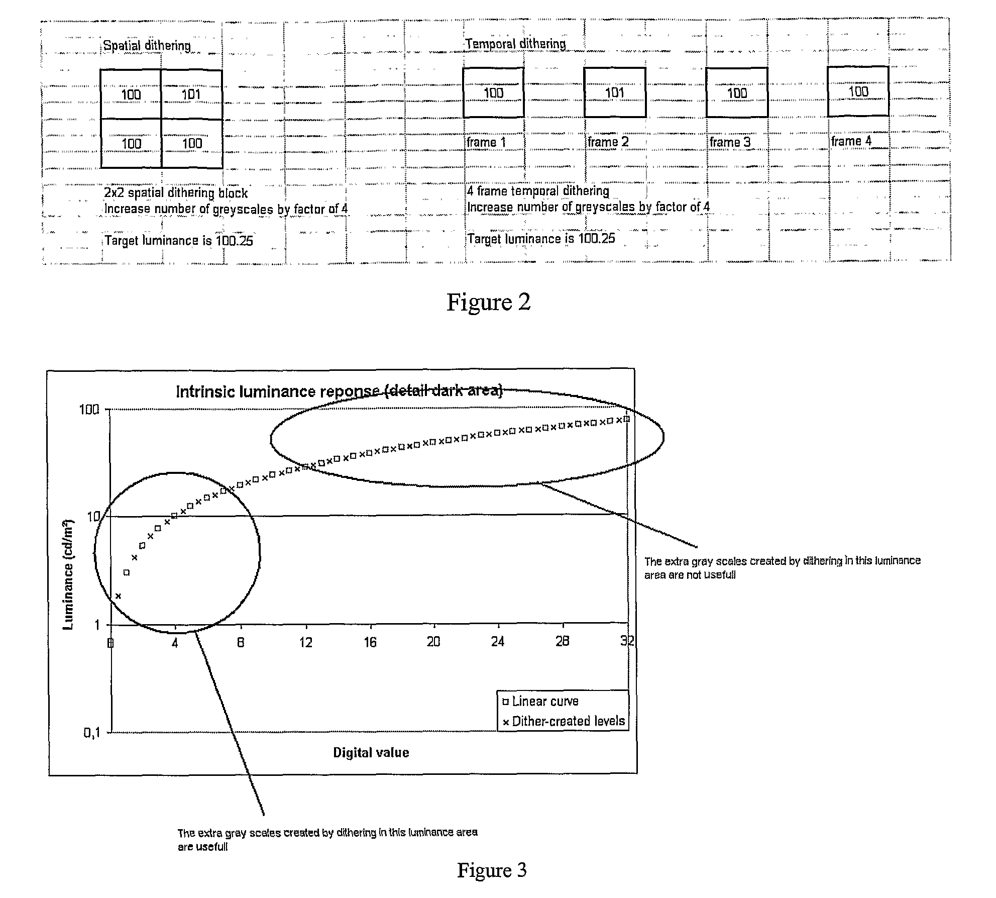
An important disadvantage of temporal dithering is that artefacts are introduced when displaying moving images.
Especially when the dithering takes place over a large number of frames this becomes a severe problem.
This is a disadvantage because typically a lot more greyscales are needed in the lower luminance range while this is not a requirement in the higher luminance range (see FIG. 3).
Of course at the same time many non-useful greyscales are created in all other luminance areas and therefore a lot of created greyscales are effectively wasted.
Note that the same problems are present in displaying colours on colour displays.
In this case the problem is having enough luminance and colour tints typically at the lower luminance values.
One problem with these display systems is that although they are only capable of showing grey tones still there is an important colour difference between the individual grey levels.
This difference in colour coordinates can easily be perceived by the user of the display and can both be disturbing and even have a negative impact on the performance.
Research has shown that changing the colour temperature of the medical images has a negative impact on the accuracy of the diagnosis.
The plots in FIG. 6 show that “whitepoint tuning” is only a small part of the solution because the colour temperature of grey levels other than full white are still not correct because of the colour-shift of the monochrome LCD.
However, there is also a colour shift problem present with colour display systems. FIG. 4 shows an example of (x, y) chromaticity coordinates in function of driving level and this for a colour display system.
This is because it is not possible to decrease the amount of blue because the blue was already driven at minimum digital driving level zero.
A first disadvantage is the decrease of contrast ratio of the display system.
A second disadvantage is that the colour gamut of the display system is reduced because the lookup-tables will cause mixing of the display primaries instead of using the pure primaries and this for multiple (R, G, B) values.
A third disadvantage is that the number of available colours is reduced.

Method used


Image

  • Backlight Modulation For Display
  • Backlight Modulation For Display
  • Backlight Modulation For Display

Examples


Embodiment Construction

[0042] The present invention will be described with respect to particular embodiments and with reference to certain drawings but the invention is not limited thereto but only by the claims. The drawings described are only schematic and are non-limiting. In the drawings, the size of some of the elements may be exaggerated and not drawn on scale for illustrative purposes. Where the term “comprising” is used in the present description and claims, it does not exclude other elements or steps.

[0043] Furthermore, the terms first, second, third and the like in the description and in the claims, are used for distinguishing between similar elements and not necessarily for describing a sequential or chronological order. It is to be understood that the terms so used are interchangeable under appropriate circumstances and that the embodiments of the invention described herein are capable of operation in other sequences than described or illustrated herein.

[0044] The embodiments described relat...


PUM


Abstract

A display ( 10 ) has a non pixel addressable backlight ( 130 ), having a temporal modulation applied, a pixel addressable LCD ( 120 ) in an optical path and the pixel addressable part being arranged to output each pixel of a frame as a temporal sequence of output values unrelated to colour components of the pixel, different values of the sequence coinciding with different output levels of the modulated non pixel addressable part. The apparent luminance or colour of the pixels can be made to take intermediate values between the gradations dictated by the stepsize corresponding to a least significant bit of the pixel addressable part, to enable more accurate reproduction of both colour and greyscale images. Additional intermediate output levels are concentrated at low illumination levels. A convertor generates a temporal modulation of the pixels for the LCD according to a value of the pixels in an input signal, and synchronized to the temporal modulation of the backlight.

Description

FIELD OF THE INVENTION [0001] The present invention relates to displays, to convertors for displays, and to methods of configuring such displays. Monochrome and colour displays, and emissive, transmissive, reflective and trans-reflective display technologies fulfilling the feature that each pixel or sub-pixel is individually addressable, can be used. DESCRIPTION OF THE RELATED ART [0002] At present, most matrix based display technologies are technologically immature compared to long established electronic image forming technologies such as Cathode Ray Tubes (CRT). As a result, some image quality deficiencies exist and cause problems for the acceptance of these technologies in certain applications, as will now be explained. [0003] A first disadvantage of current matrix displays, such as but not limited to LCD displays and DMD / DLP (Digital Micromirror Devices / Digital Light Processing: pixels are formed by very small controllable mirrors that can be electronically set to one of two pos...

Claims


Application Information

Patent Timeline
IPC IPC(8): G09G5/10
CPCG09G3/20G09G3/2025G09G3/2044G09G3/2077G09G3/3406G09G2320/0666G09G2310/0237G09G2320/0276G09G2320/0633G09G2320/0646G09G2310/0235
Inventor KIMPE, TOM
Owner BARCO NV
Learn More