

Hearing aid device
- Summary
- Abstract
- Description
- Claims
- Application Information
AI Technical Summary
Benefits of technology
Problems solved by technology
Method used
Image

Examples
Embodiment Construction
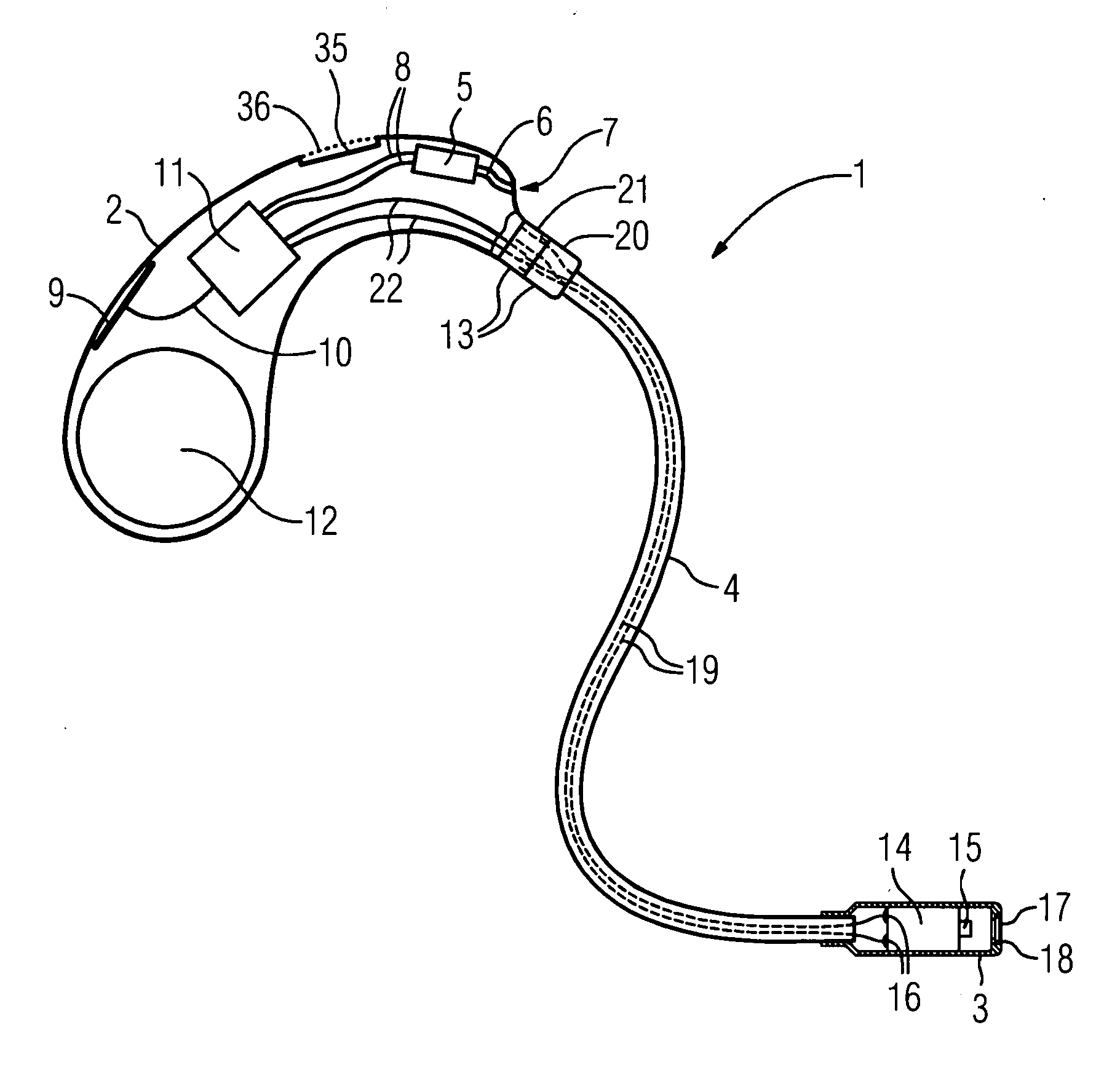
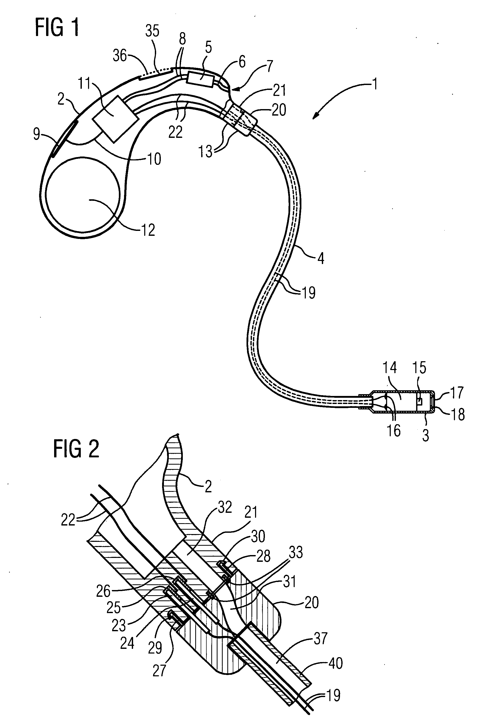
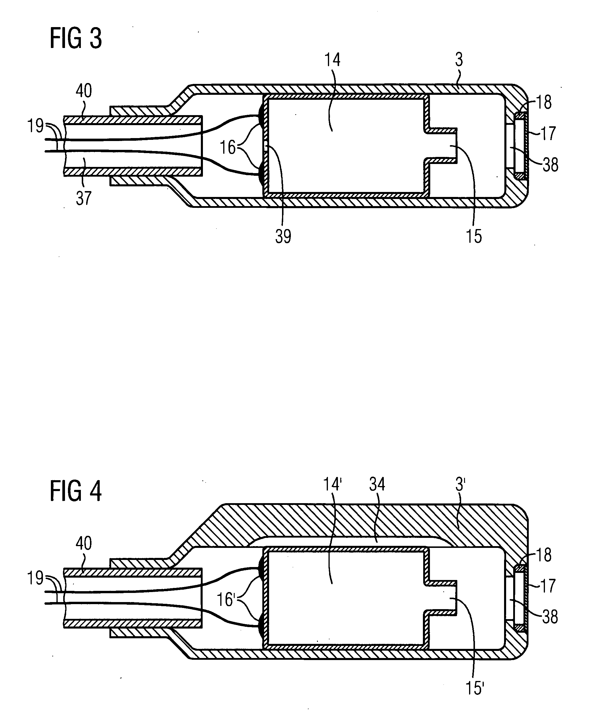
[0021] Externally, the hearing aid device 1 according to the exemplary embodiment is composed of the three segments; device element 2, earmold 3 and connecting piece 4. The device element 2 is designed to be worn behind the ear of a user and the earmold 3 with the receiver 14 contained therein is inserted into the auditory canal of the user when being worn. The earmold 3 is dimensioned such that it does not seal the auditory canal of the user. The hearing aid device 1 is thus designed for the “open supply” of the user. The device element 2 includes a microphone 5, which records an acoustic input signal by way of an acoustic channel 6 and a housing opening 7. In order to protect against contamination, the housing opening 7 can be provided with an air-permeable cover. The microphone 5 converts the acoustic input signal into an electrical input signal, which is fed to a signal processing unit 11 by way of electrical conductors 8. The processing and preferably frequency-dependent amplif...
PUM
 Abstract
Description
Claims
Application Information