Stent with flexible hinges

a stent and hinge technology, applied in the field of expandable stents, can solve the problems of keeping the stent in an expanded condition, and achieve the effects of less flexible, consistent expansion, and convenient introduction of the sten

Inactive Publication Date: 2008-04-24
INNOVATIONAL HLDG LLC
View PDF4 Cites 22 Cited by
  • Summary
  • Abstract
  • Description
  • Claims
  • Application Information

AI Technical Summary

Benefits of technology

[0002]It is desirable to provide flexibility in stents to facilitate introduction of the stent into vessels that are difficult to reach. Often, however, characteristics of the stent that provide longitudinal flexibility that is desirable when introducing the stent into the vessel can be disadvantageous in terms of keeping the stent in an expanded condition. For example, stents formed from interconnected rings with closed cell structures or generally diamond-shaped cells are typically less flexible than stents formed from one or more helices, but are usually more uniformly and consistently expandable than helical stents. It is desirable to provide a stent with substantial flexibility that is adapted to be expanded in a uniform and consistent fashion.
[0003]In WO 03 / 015664, which is incorporated by reference, a stent having interconnected struts with openings for drug delivery is disclosed. However, elements for bridging the struts are generally thinner and spaced further apart than the struts. Thus, for such drug-eluting stents, the bridging element can provide an area of reduced or less consistent drug delivery. It is desirable to provide a drug-eluting stent in which areas of reduced or less consistent drug delivery can be reduced.

Problems solved by technology

Often, however, characteristics of the stent that provide longitudinal flexibility that is desirable when introducing the stent into the vessel can be disadvantageous in terms of keeping the stent in an expanded condition.
However, elements for bridging the struts are generally thinner and spaced further apart than the struts.

Method used


Image

  • Stent with flexible hinges
  • Stent with flexible hinges
  • Stent with flexible hinges

Examples


Embodiment Construction

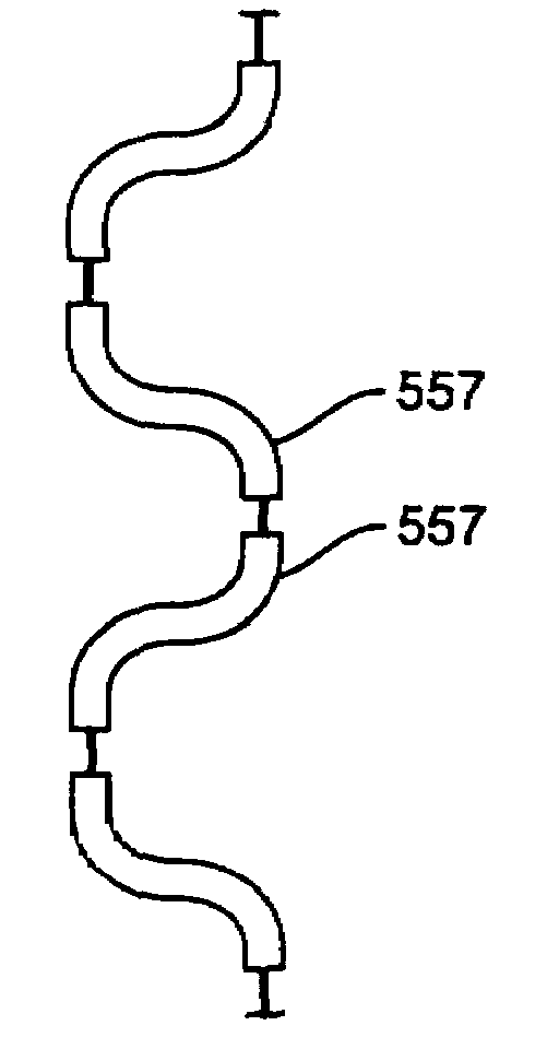
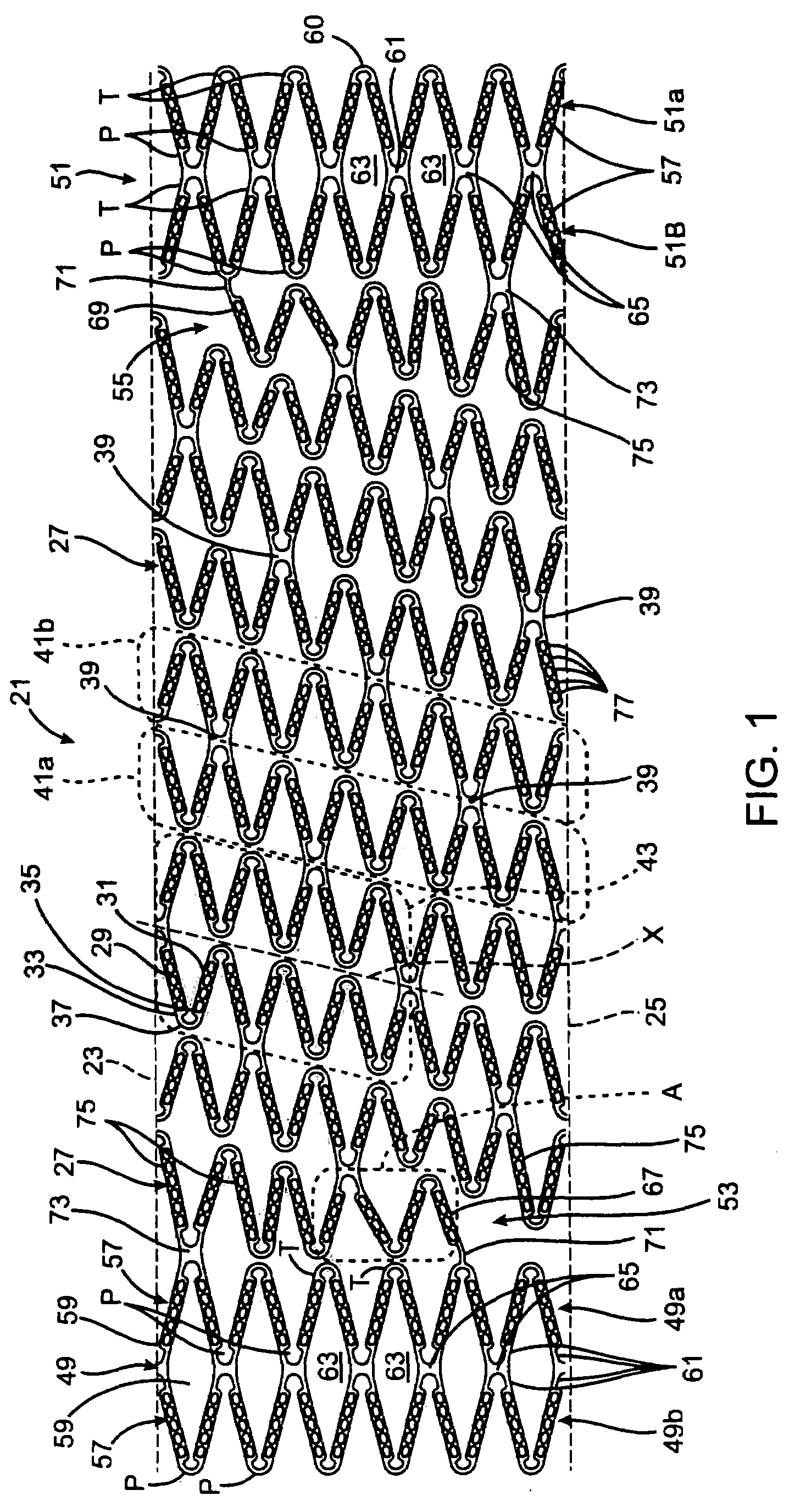
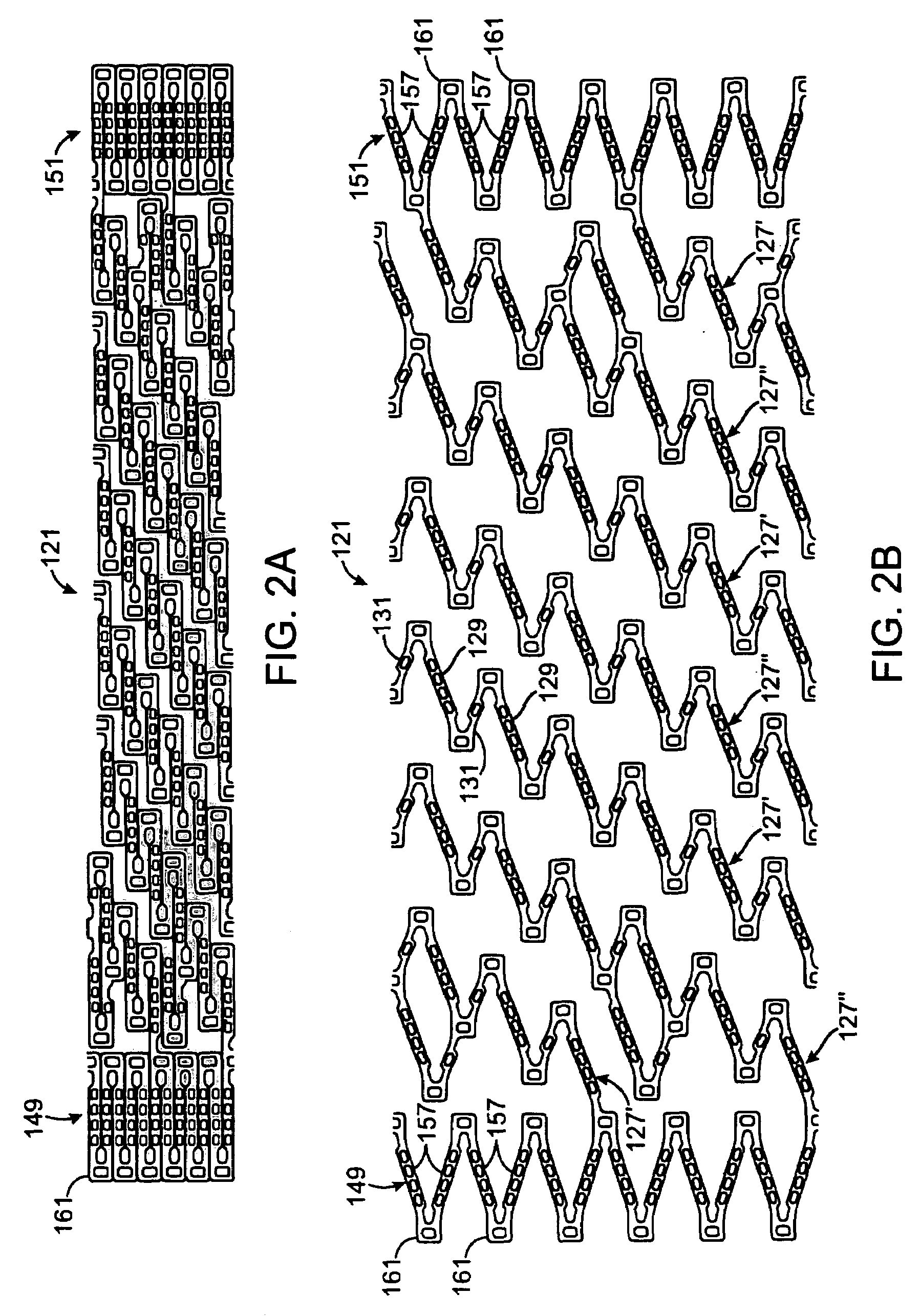
[0022]A helical stent 21 according to an embodiment of the present invention is shown in FIG. 1. The stent 21 is shown in FIG. 1 as it would appear if the stent were in an at least partially expanded condition and cut along its length. More particularly, the stent 21 shown in FIG. 1 is shown in the form in which it would appear if it were cut along its length and the cut article was laid out flat. The stent 21 can be formed in any suitable manner, such as by being laser cut from a tube made of a suitable material including cobalt chromium alloys, stainless steel alloys or nickel titanium alloys. In an “as cut” version of the stent 21, top and bottom edges 23 and 25 would ordinarily be joined together. FIGS. 2A and 2B show another embodiment of a stent 121 in an unexpanded and an at least partially expanded condition, respectively, and cut along its length. The present invention will be described as a vascular stent, such as a coronary or peripheral stent. However, the stent structur...


PUM


Abstract

A helical stent includes at least one helical winding. Each helical winding includes a plurality of alternating long struts and short struts, ends of at least some of the long struts being joined to an end of an adjacent short strut by a flexible hinge arrangement, the struts being substantially rigid. The stent also includes at least one interconnection member connecting a hinge arrangement on one turn of the at least one winding with a hinge arrangement on an adjacent turn of the at least one winding. Fewer than all hinge arrangements on the at least one helical winding are connected to other hinge arrangements by an interconnection member.

Description

BACKGROUND AND SUMMARY[0001]The present application relates to expandable stents and, more particularly, to expandable stents with flexible hinges.[0002]It is desirable to provide flexibility in stents to facilitate introduction of the stent into vessels that are difficult to reach. Often, however, characteristics of the stent that provide longitudinal flexibility that is desirable when introducing the stent into the vessel can be disadvantageous in terms of keeping the stent in an expanded condition. For example, stents formed from interconnected rings with closed cell structures or generally diamond-shaped cells are typically less flexible than stents formed from one or more helices, but are usually more uniformly and consistently expandable than helical stents. It is desirable to provide a stent with substantial flexibility that is adapted to be expanded in a uniform and consistent fashion.[0003]In WO 03 / 015664, which is incorporated by reference, a stent having interconnected st...

Claims


Application Information

Patent Timeline
Patent Type & Authority Applications(United States)
IPC IPC(8): A61F2/88
CPCA61F2/88A61F2/91A61F2250/0068A61F2002/91558A61F2/915
Inventor SHANLEY, JOHN F.MURALIDHARAN, PRASANNA VENKATESH
Owner INNOVATIONAL HLDG LLC
Why Eureka
Try Eureka