Form-fitting solar panel for roofs and roof vents

a solar panel and roof technology, applied in the field of roofs for buildings, can solve the problems bulky solar panels, and not blending in with the roof covering, and achieve the effect of reducing the attractiveness of the roo

Active Publication Date: 2008-05-01
ODANIELS LLC
View PDF107 Cites 68 Cited by
  • Summary
  • Abstract
  • Description
  • Claims
  • Application Information

AI Technical Summary

Benefits of technology

[0008]One problem with conventional roofs having solar panels is that the solar panels tend to be bulky and do not blend in with the roof covering. For example, the roof covering may comprise shingles (made of various materials, e.g., steel, composition, wood), or tiles (made of metal, clay, concrete, plastic, or other materials) of any of a variety of different shapes and sizes. The solar panels thus tend to stand out visibly and reduce the attractiveness of the roof.

Problems solved by technology

One problem with conventional roofs having solar panels is that the solar panels tend to be bulky and do not blend in with the roof covering.
The solar panels thus tend to stand out visibly and reduce the attractiveness of the roof.

Method used


Image

  • Form-fitting solar panel for roofs and roof vents
  • Form-fitting solar panel for roofs and roof vents
  • Form-fitting solar panel for roofs and roof vents

Examples


Embodiment Construction

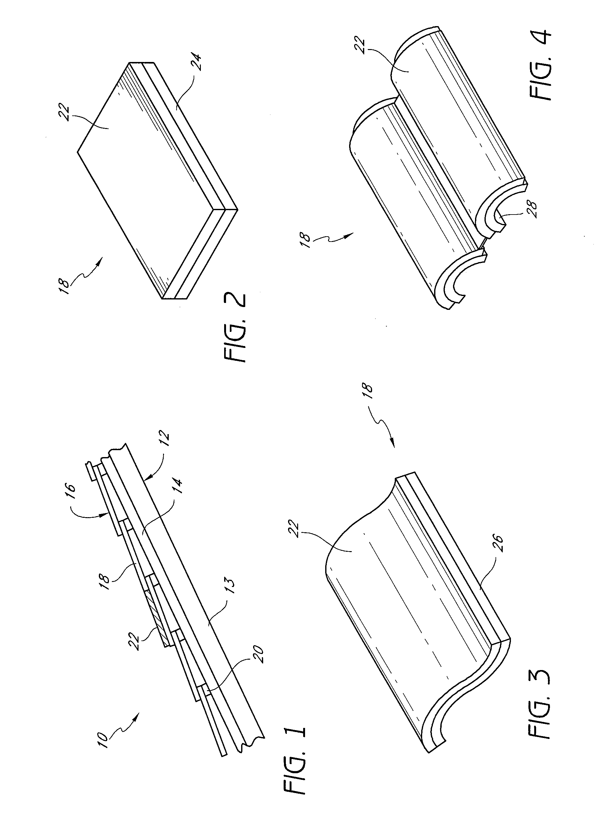
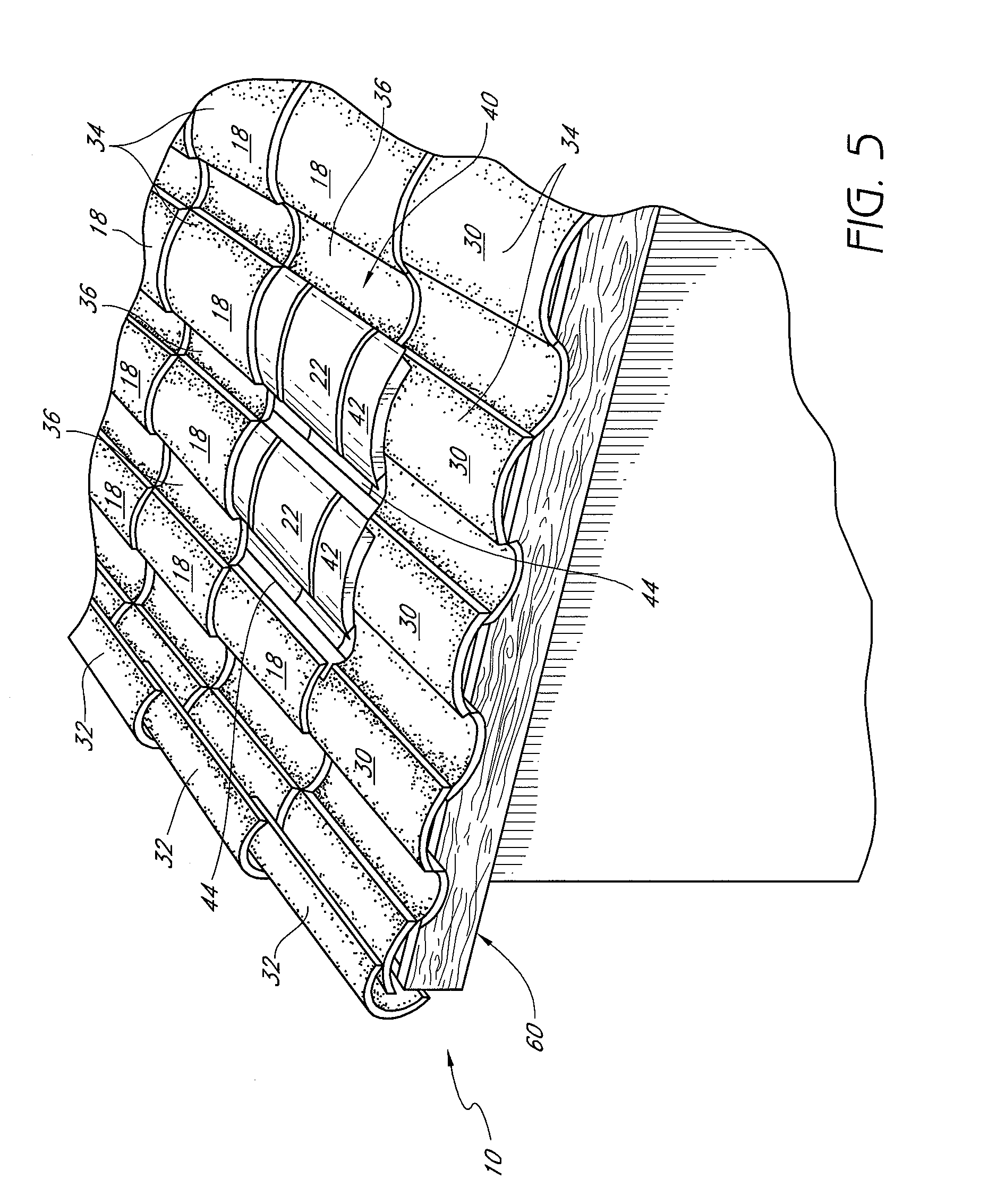
[0028]FIG. 1 shows an exemplary tile roof 10 comprising a roof frame 12, a roof deck 14 supported on the roof frame 12, and a layer 16 of roof cover elements. In this embodiment, the roof cover element layer 16 comprises a layer of tiles 18. However, the roof cover elements may alternatively comprise other elements, such as shingles (e.g., made of steel, metal, composition material, wood, or other materials). The tiles 18 may be formed of, e.g., metal, clay, concrete, plastic, or other materials. The roof frame 12 may comprise rafters 13 that extend from an upper ridge (not shown) of the roof to a lower eave (not shown). The roof frame 12 may also comprise purlins (not shown) that extend substantially parallel to the ridge and eave and substantially perpendicular to the rafters 13. The roof deck 14 typically comprises plywood, metal, or some type of alloy (e.g., steel) sheeting. The roof cover element layer 16 typically comprises a plurality of tiles 18 supported on battens 20 orien...


PUM


Abstract

A roof of a building is provided. The roof comprises a roof frame, a layer of curved roof cover elements (e.g., tiles) above the roof frame, and a solar panel secured to one or more of the roof cover elements. The solar panel substantially conforms to one or more curved surfaces of the one or more roof cover elements. Another aspect provides a roof comprising a roof frame, a layer of curved roof cover elements (e.g., tiles) above the roof frame, a vent member within the roof cover element layer, and a solar panel. The vent member has a curved surface and is sized and shaped to mimic the appearance of one or more of the roof cover elements. The vent member also has an opening allowing a ventilation airflow from the building interior toward an airspace above the vent member and the roof cover element layer. The solar panel is secured to and substantially conforms to the curved surface of the vent member.

Description

CLAIM FOR PRIORITY[0001]This application claims the priority benefit under 35 U.S.C. §119(e) of Provisional Application Serial No. 60 / 854,647, filed Oct. 25, 2006. The full disclosure of this priority application is incorporated herein by reference.CROSS-REFERENCE TO RELATED APPLICATIONS[0002]The present application incorporates by reference the entire disclosures of (1) U.S. Pat. No. 6,050,039; (2) U.S. Pat. No. 6,129,628; (3) U.S. Patent Application Publication No. 2005-0239394-A1; and (4) U.S. Provisional Application No. 60 / 793,337, filed Apr. 18, 2006, entitled “Automatic Roof Ventilation System.”BACKGROUND OF THE INVENTION[0003]1. Field of the Invention[0004]The present invention relates generally to roofs for buildings, and specifically to integration of solar panels into roofs.[0005]2. Description of the Related Art[0006]For decades, builders and solar power companies have installed solar panels onto the roofs of buildings. The solar panels absorb solar radiation that can be ...

Claims


Application Information

Patent Timeline
Patent Type & Authority Applications(United States)
IPC IPC(8): E04D13/18
CPCE04D1/30H02S20/25Y02B10/12E04D2001/309Y02E10/50Y02B10/10E04D1/2918
Inventor O'HAGIN, CAROLINA STOLLENWERKDANIELS, GREGORY S.
Owner ODANIELS LLC
Why Eureka
Try Eureka