Simplified oil sampling assembly

a technology of oil sampling and assembly, applied in the field of oil sampling assembly, can solve the problems of serious damage to the sampler, inability to run the engine or machinery, and difficulty in oil sampling at operating temperature, so as to prevent any type of cross contamination, facilitate the transport, and eliminate the effect of “cross contamination

Inactive Publication Date: 2008-05-01
CAMPBELL D MICHAEL +1
View PDF14 Cites 9 Cited by
  • Summary
  • Abstract
  • Description
  • Claims
  • Application Information

AI Technical Summary

Benefits of technology

[0010]More specifically, the various preferred embodiments of the sampling assembly of the present invention facilitates the removal of an oil sample from the oil circulating system of engines, machinery, etc. without coming into direct contact with the oil. Further, after operation of the engine or machinery from which the sample is obtained, the oil may be allowed to cool to a temperature which is sufficiently low to eliminate or significantly reduce the possibilities of any damage being done to a user in the unlikely event of an inadvertent spill or contact between the oil sample and the individual taking the sample. Moreover, the collected oil sample will be representative, in terms of contained contaminants, of the oil circulating throughout the engine or machinery.
[0011]Accordingly, the present invention comprises a housing connected “inline” with the oil circulating system of the engine, machinery or like device from which the oil sample in obtained. Moreover, the housing includes an inlet assembly and an outlet assembly both connected in direct fluid communication to the oil circulating system. The sampling assembly of the present invention further includes a container removably connected to the housing. The container is dimensioned, configured and comprises an overall structure which facilitates the collection of an oil sample therein directly from the oil circulating system. Collection of the oil sample in a safe and efficient manner is facilitated by virtue of the fact that the interior of the container is also disposed in fluid communication with the oil circulating system through both the inlet-assembly and the outlet assembly of the housing.
[0013]Due to the fact that the container is removably connected to the housing in at least partially sealing engagement therewith, the collection of the oil sample retained within the interior of the container is accomplished by detachment of the container from the housing and the placement of a closure over the open end or other receiving portion of the container. In addition, the container and the closure are structured to define a package or shipping container which facilitates the transport, utilizing any conventional means, of the container and the collected oil sample to a testing or analysis facility for determination of the contaminants therein.
[0015]Another advantage which further evidences the versatility of the present invention is the ability to eliminate “cross-contamination” between engines, such as when multiple engines are being sampled. More specifically, upon the removal of one container for purposes of sampling the oil retained therein, a new, replacement container may be substituted therefore. Such a replacement container may have been previously used and if so, the replacement container will be thoroughly cleaned so as to prevent any type of cross contamination. Such cross contamination may is a possibility when containers are repeatedly used with different engines being sampled. Accordingly, either a replacement container, which has been cleaned, will be used upon the removal of an original container or alternatively a new, previously unused replacement container will be substituted therefore.
[0016]Therefore, certain disadvantages associated with conventional techniques and procedures for obtaining oil samples are overcome by virtue of collecting the oil sample within the container and not requiring it to be removed there from for purposes of transporting the oil sample to a testing facility. As a result the chance of contact or exposure of an individual to the collected oil is significantly reduced or eliminated. In addition once the engine or machinery being maintained has been shut down, the oil sample contained within the container may be allowed to cool before the container and the collected oil sample is removed from the housing. This further increases the safety factor in reducing the possibility of harm to the individual collecting the oil sample.
[0018]In at least one preferred embodiment the delivery device includes an elongated delivery tube or conduit having one end connected to the housing in fluid communication with the inlet assembly and the opposite end defined by a delivery port disposed in direct fluid delivering relation to the contaminant collection portion of the container. Therefore when the engine or machinery is restarted, oil will flow from the oil circulating system directly through the elongated conduit of the delivery device and exit through the delivery port directly into the area which substantially defines the contaminant collecting portion. As such, any contaminants settling or collecting in this area will be distributed throughout the remaining oil within the container. Accordingly, the structural and operative features of the delivery device assure that any settled contaminants or other heavy material collected in the lower areas or other contaminant collecting portion of the container will be redistributed throughout the oil within the container each time a start-up of the engine or machinery occurs. Such contaminants will again flow back into the oil circulating system and become a part thereof. Continuous flow of oil through the aforementioned path of fluid flow, from the inlet assembly through the delivery device, into the interior of the container and back out through the outlet assembly, will assure a “fresh” oil sample being disposed within the container and having representative contaminants contained therein.

Problems solved by technology

Accordingly, problems and disadvantages associated with current, known or conventional oil sampling techniques include, among others, the necessity of operating an engine or machinery under normal operating conditions to ensure a complete heating of the oil within the circulating system of the engine or machinery to normal operating temperatures immediately preceding the collection of the oil samples for analysis.
Sampling of oil at operating temperatures is not only difficult and inconvenient, using conventional procedures, but also can be dangerous in that normal operating oil temperatures can range from 190-220° F. Accordingly, the danger of coming into direct contact with hot oil in an attempt to remove small quantities thereof for sampling can result in serious damage to the sampler.
Additional disadvantages are associated with the conventional use of a suction pump or other extraction device used to remove the oil sampling from the crank case, oil reservoir, etc.
The collected oil sample is thereby transferred while at potentially dangerous operating temperatures to a separate container.
Therefore, while the engines incorporating sampling ports of the type set forth above may simplify and to a certain extent facilitate the process of obtaining hot oil samples, it does not eliminate the requirement of running the engine or machinery for a period of time to ensure the collected oil is at normal operating temperature.
Other disadvantages associated with conventional oil sampling assemblies and procedures also lack the assurance that all contaminants are equally distributed throughout the oil being collected and / or circulated.
A lack of consistent contaminant distribution throughout the oil circulating system may result in the collected oil sample not being accurately representative of the oil contained in the oil reservoir and / or oil circulating system in terms of contaminant content.

Method used


Image

  • Simplified oil sampling assembly
  • Simplified oil sampling assembly
  • Simplified oil sampling assembly

Examples


Embodiment Construction

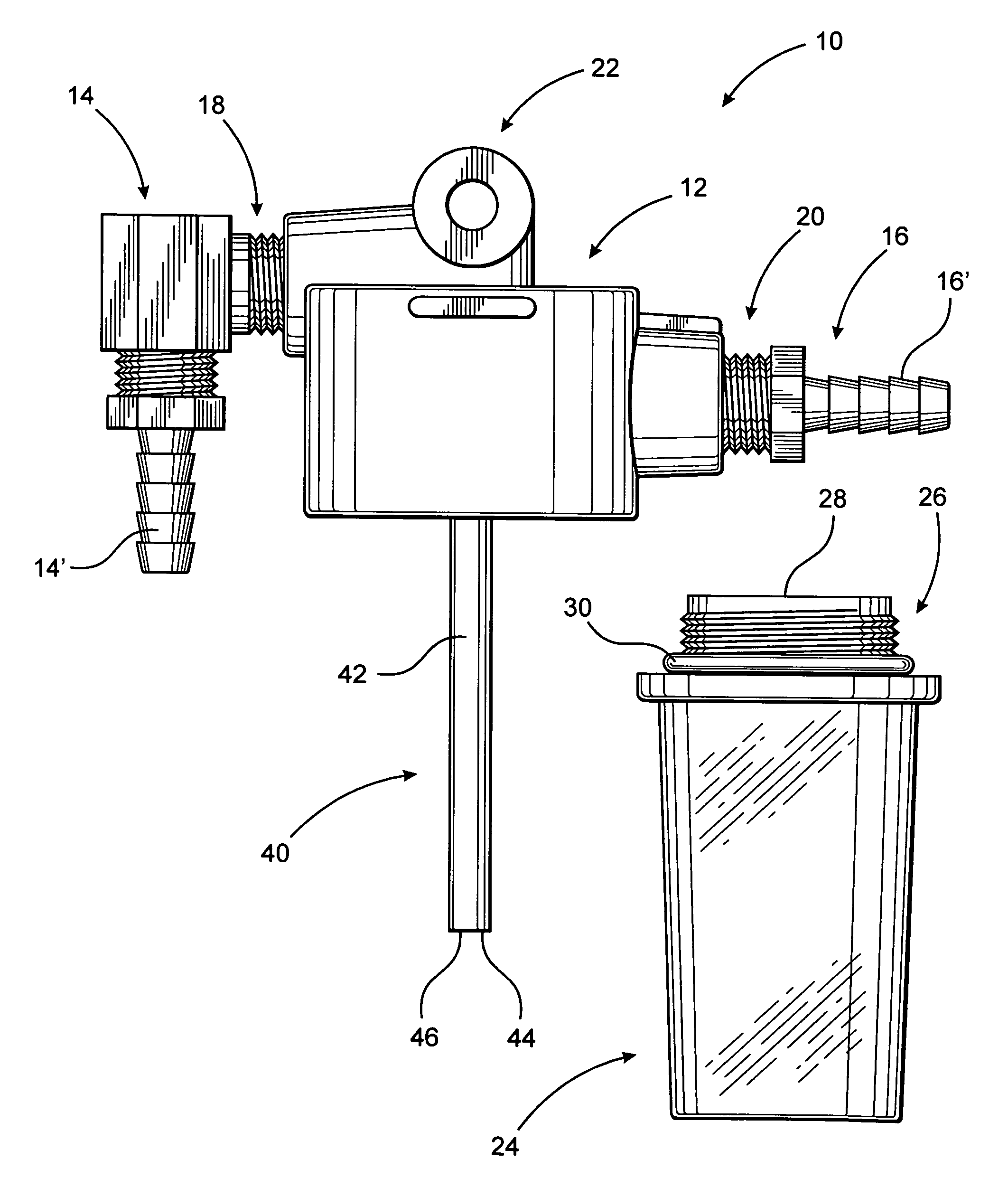
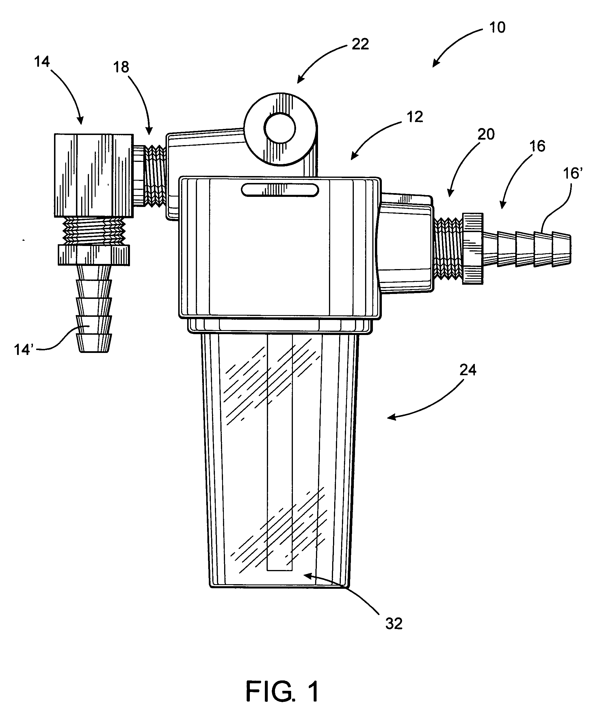
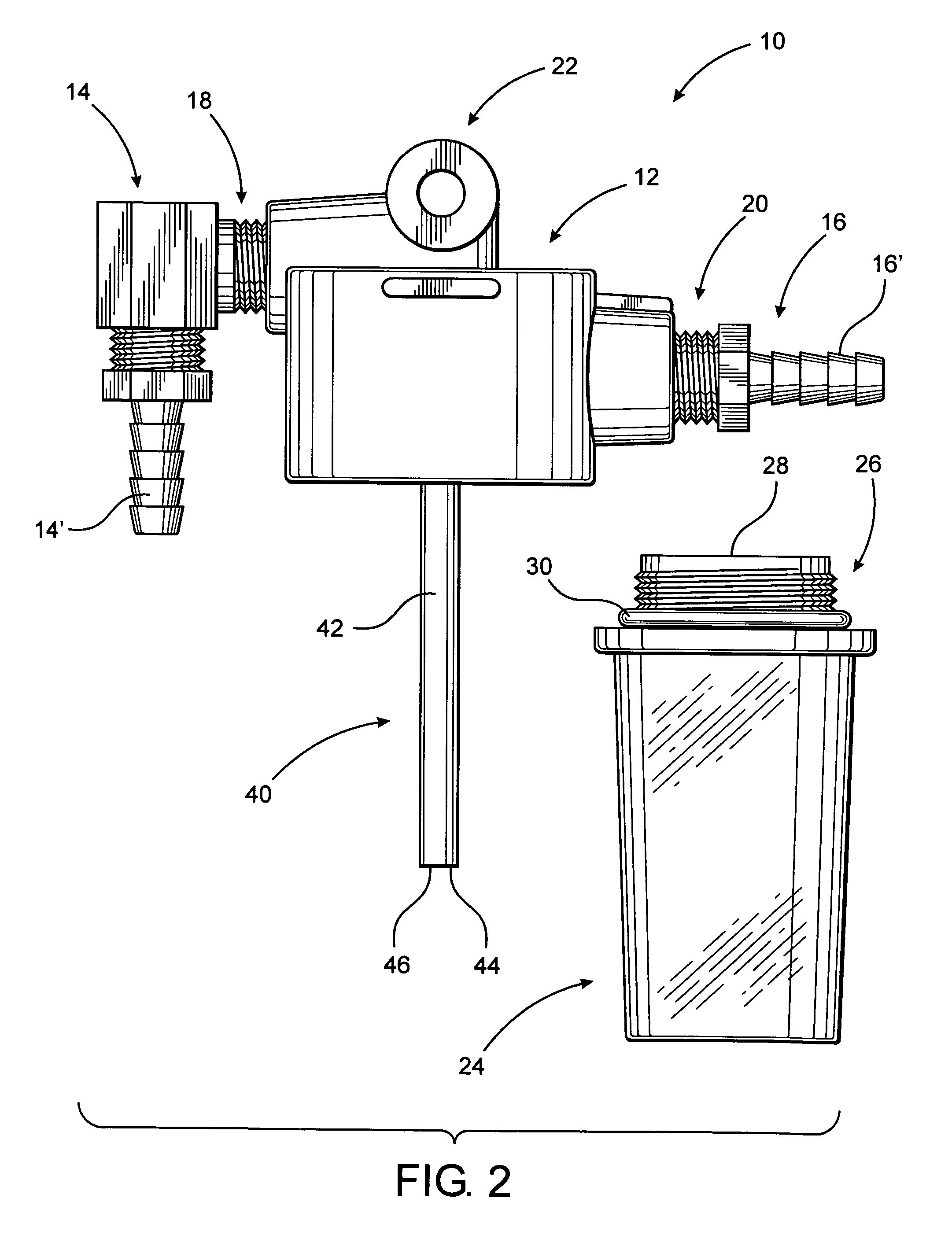
[0028]As shown in the accompanying drawings, the present invention is directed to a sampling assembly generally indicated as 10 which is adapted for collecting oil samples from engines, machinery, or other devices. As practically applied, the sampling assembly 10 is connected in fluid communication with an oil circulating system of the engine, machinery, etc.

[0029]As schematically represented in FIG. 3 and for purposes of clarity, the engine, machinery, etc. from which the oil sample is collected is generally indicated as 100 and includes a crankcase, oil reservoir or the like 102 as well as an oil circulating system 104. As schematically represented, the oil circulating system defines the path of travel of the oil as it flows throughout appropriate and predetermined portions of the engine, machinery, etc. 100. As will be explained in greater detail hereinafter, the sampling assembly 10 is connected in fluid communication with the oil circulating system 104. As a result, a continuou...


PUM

PropertyMeasurementUnit
temperaturesaaaaaaaaaa
areaaaaaaaaaaa
lengthaaaaaaaaaa

Abstract

The present invention is directed to an oil sampling assembly structured to collect an oil sample from the oil circulating system of an engine or other device and including a housing connected in fluid communication with the oil circulating system and having a container removably connected thereto. During operation of the oil circulating system a continuous flow of oil into and out of the container will occur. When the oil circulating system is not operating, oil and any contaminants contained therein will collect within the container. The container and oil sample is detached from the housing, replaced by another container, and connected to a closure for transport to a testing facility.

Description

BACKGROUND OF THE INVENTION[0001]1. Field of the Invention[0002]The present invention is directed to an oil sampling assembly wherein an oil sample and representative contaminants contained therein are collected within a container disposed in fluid communication with the oil circulating system of the engine or machinery being sampled. The container, once removed from its communicating relation with the oil circulating system is structured to define a shipping package for the transport of oil to a testing facility.[0003]2. Description of the Related Art[0004]The collection and testing of oil samples from engines, machinery, etc. are well known and popular practices and intended to assure their efficient and long life operation by determining what contaminants exist within the oil circulating system. In preferred maintenance systems, oil sampling is conducted on a scheduled, predetermined, periodic basis and is a process by which a small amount of oil is extracted from the crank case,...

Claims


Application Information

Patent Timeline
Patent Type & Authority Applications(United States)
IPC IPC(8): G01N1/00
CPCG01N33/28G01N1/2035
Inventor CAMPBELL, D. MICHAELZACKS, JACK E.
Owner CAMPBELL D MICHAEL
Why Eureka
Try Eureka