
Staggered guard ring structure

a guard ring and ring structure technology, applied in the direction of semiconductor devices, electrical equipment, semiconductor/solid-state device details, etc., can solve the problems of cracks propagating from the dicing area, crack stop structure b, b> to fail, etc., and achieve the effect of stopping cracks

Inactive Publication Date: 2008-05-01
KK TOSHIBA
View PDF15 Cites 36 Cited by
  • Summary
  • Abstract
  • Description
  • Claims
  • Application Information

AI Technical Summary

Benefits of technology

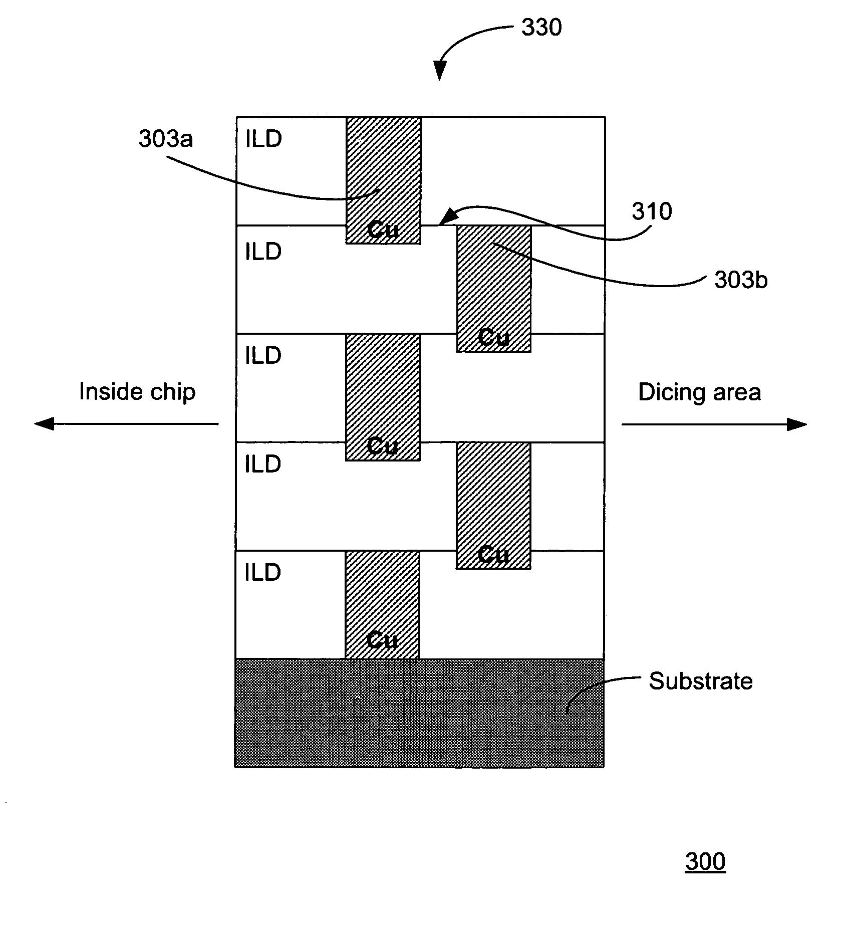
[0009]Embodiments of the present invention provide a staggered guard ring structure for stopping cracks from propagating during a dicing operation or by suffering mechanical stress after packaging.
[0016]In all embodiments of the invention, the ILD-ILD interfaces and the metal-metal interfaces do not lie in a single geometric plane. No planar relationship therefore exists between the metal-metal interfaces and the ILD-ILD interfaces. By breaking the continuity between the two types of interfaces, embodiments of the invention can prevent the metal layers from delaminating and effectively stop cracks from propagating into the active circuit area of a chip, thereby overcoming the aforementioned weakness in conventional crack stop structures.

Problems solved by technology

During the dicing operation, cracks may develop and propagate from the dicing area.
Such cracks may be caused by chips and / or cracks formed along edges of the IC chips during the dicing operation.
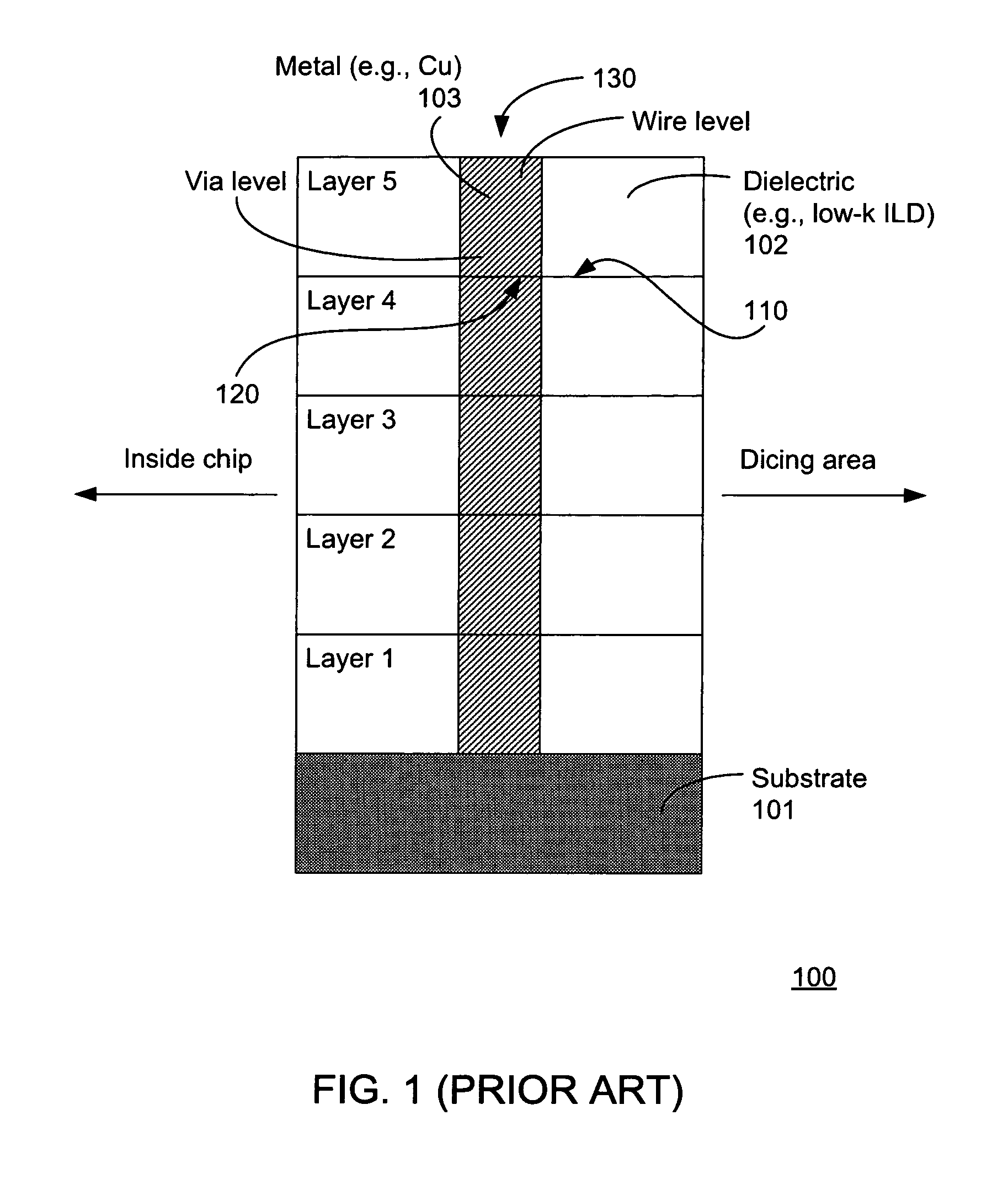
One weakness of this conventional crack stop structure is that cracks propagating through ILD-ILD interface 110 can easily delaminate metal-metal interface 120, causing crack stop structure 130 to fail to stop cracks from coming into the active circuit area inside of chip 100.
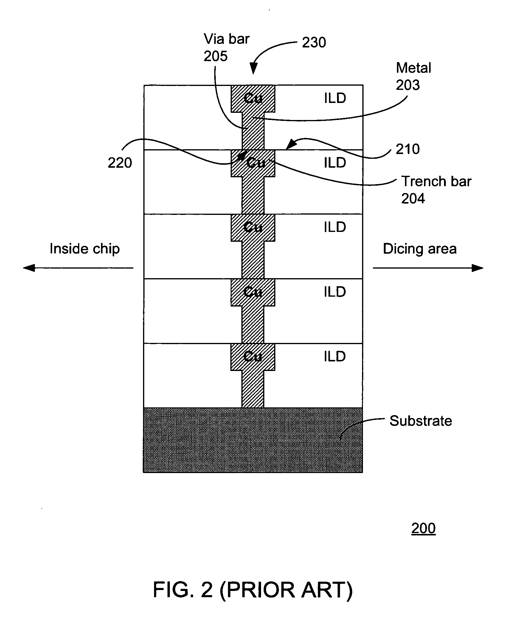
Consequently, this conventional crack stop structure also suffers from the aforementioned weakness in that cracks propagating through ILD-ILD interface 210 can easily delaminate metal-metal interface 220, causing the crack stop structure 230 to fail to stop cracks from coming into the active circuit area of chip 200.
This planar relationship between two different types of interfaces can cause the metal layers to delaminate undesirably.

Method used


Image

  • Staggered guard ring structure
  • Staggered guard ring structure
  • Staggered guard ring structure

Examples


Embodiment Construction

[0029]The present invention and various features and advantageous details thereof will now be described with reference to the exemplary, and therefore non-limiting, embodiments that are illustrated in the accompanying drawings. Descriptions of known techniques and technologies may be omitted so as not to unnecessarily obscure the invention in detail. It should be understood, however, that the detailed description and the specific examples, while indicating preferred embodiments of the invention, are given by way of illustration only and not by way of limitation. Various substitutions, modifications, additions and / or rearrangements within the spirit and / or scope of the underlying inventive concept will become apparent to those skilled in the art from this disclosure.

[0030]Embodiments of the present invention provide a staggered guard ring structure for stopping cracks from propagating during a dicing operation or by suffering mechanical stress after packaging.

[0031]The guard ring str...


PUM


Abstract

Embodiments of the present invention provide staggered guard ring structures for stopping cracks from propagating during a dicing operation or by suffering mechanical stress after packaging. In one embodiment, a guard ring structure may comprise staggered metal bars, each of which extends into the ILD underneath it. In one embodiment, the extended portion of a metal bar may overlap a portion of another metal bar underneath it. In one embodiment, the bottom portion of a metal bar extends into the underlying substrate. In all embodiments of the invention, the metal-metal interfaces and the ILD-ILD interfaces do not lie on the same plane, effectively stopping cracks from propagating into the active circuit area through delaminated interfaces.

Description

FIELD OF THE INVENTION[0001]This invention relates generally to crack stop structures. More particularly, embodiments of the present invention relate to staggered guard ring structures and methods of making the same.BACKGROUND OF THE INVENTION[0002]Integrated circuit (IC) chips can be fabricated on a wafer and separated into individual chips by way of a dicing operation. During the dicing operation, cracks may develop and propagate from the dicing area. Such cracks may be caused by chips and / or cracks formed along edges of the IC chips during the dicing operation. Crack stop structures are useful in preventing the cracks from propagating into the active circuit area of the IC chips. A crack stop structure can be formed as a metal stack separating the dicing area from where the active circuitry of a chip resides.[0003]FIG. 1 schematically depicts one example of a conventional crack stop structure, which can be seen as a metal interconnect structure 130 comprising a stack of metal bar...

Claims


Application Information

Patent Timeline
IPC IPC(8): H01L23/52
CPCH01L23/562H01L23/585H01L2924/0002H01L2924/00
Inventor INOHARA, MASAHIO
Owner KK TOSHIBA
Learn More