
Method and apparatus for eliminating stall and cogging in multi-phase stepping motors

a multi-phase stepping motor and stepping motor technology, applied in the direction of electric programme control, dynamo-electric converter control, instruments, etc., can solve problems such as motor stall

Inactive Publication Date: 2008-05-01
COUTU DAVID
View PDF17 Cites 22 Cited by
  • Summary
  • Abstract
  • Description
  • Claims
  • Application Information

AI Technical Summary

Benefits of technology

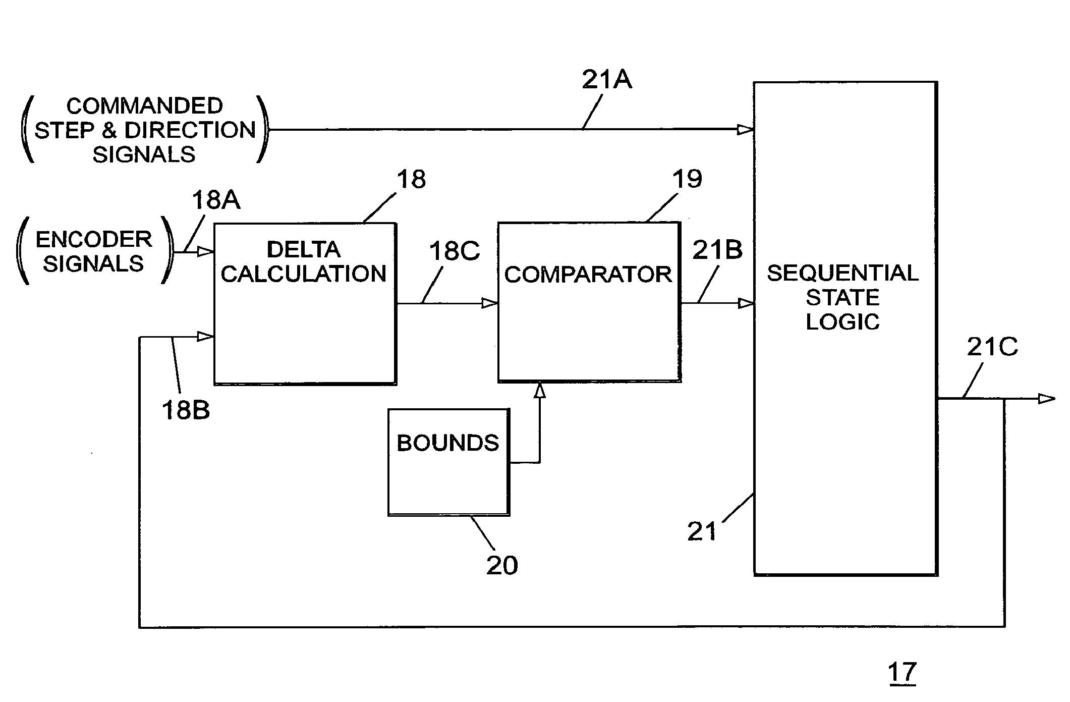
[0010]The lead or lag relationship between the stator and rotor of a stepper motor is monitored on a continuing basis to determine the possible occurrence of motor stalls and motor cogging. Digital comparators are employed to determine when such lead or lag is equal to or greater than a predetermined value and an incremental encoder provides such information in feed-back relation to thereby prevent motor stalls and motor cogging.

Problems solved by technology

One problem generally associated with such stepper motors is the possibility of motor stall when the torque generated by the associated load exceeds the motor rating.
A further problem occurs when the associated load causes the motor rotor to lead or lag the motor stator to such an extent as to cause the rotor to jump from one stable position to a new stable position, which is known as “cogging”.
In most applications, the feedback circuit for preventing stalling is incorporated within the servo-motor circuit, per se, and cannot be used with existing motors

Method used


Image

  • Method and apparatus for eliminating stall and cogging in multi-phase stepping motors
  • Method and apparatus for eliminating stall and cogging in multi-phase stepping motors
  • Method and apparatus for eliminating stall and cogging in multi-phase stepping motors

Examples


Embodiment Construction

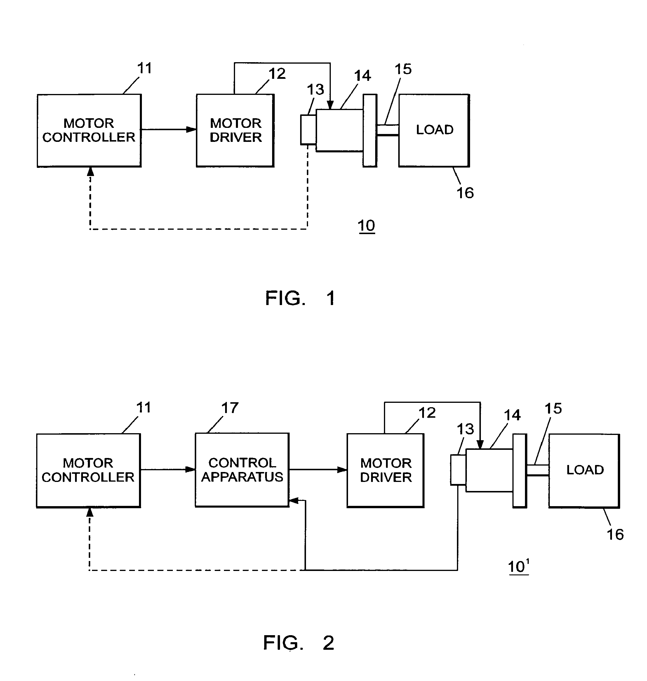
[0017]Before referring to the circuit components of the invention, as shown in FIGS. 1 and 2, the following information shown in FIG. 3 is helpful to a better understanding of the invention.

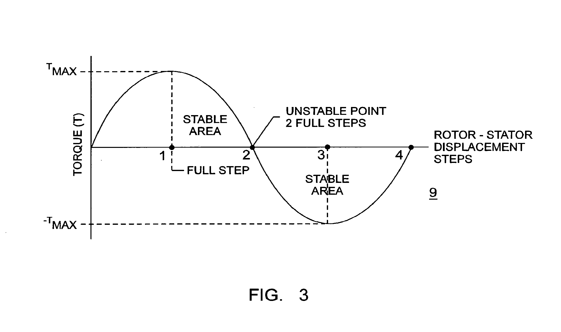
[0018]FIG. 3 represents a stepper motor torque output waveform 9 as a function of the stepper motor-stepper motor stator displacement steps.

[0019]As shown in FIG. 3, a stepper motor produces maximum torque when the rotor is leading or lagging the stator by a full step.

[0020]When the rotor reaches a lead or lag equaling 2 full steps, the motor is in a very unstable state. If the rotor is allowed to approach a lead or lag equaling 2 full steps, the rotor may jump to the next stable position. If this occurs synchronism between the commanded commutation frequency and the actual rotor frequency may be lost.

[0021]To eliminate this possibility, the rotor must be kept in the stable region indicated wherein the rotor leads or lags the stator by or near one full step, whereby the motor will produce maximum...


PUM


Abstract

The lead or lag relationship between the stator and rotor of a stepper motor is monitored on a continuing basis by an incremental encoder, in feed-back relation, and adjusts the lead or lag to within optimum range values to thereby prevent motor stalls and motor cogging.

Description

[0001]This invention relates to stepper motors such as described within U.S. Pat. No. 6,967,425 entitled “Multi-Functional Electric Stepper Motor Assembly Having Increased Motor Torque” and U.S. Pat. No. 6,879,128 entitled “Method and Apparatus For Independently Controlling Each Phase of a Multi-Phase Step Motor”, which patents are incorporated herein for purposes of reference.BACKGROUND OF THE INVENTION[0002]One problem generally associated with such stepper motors is the possibility of motor stall when the torque generated by the associated load exceeds the motor rating.[0003]A further problem occurs when the associated load causes the motor rotor to lead or lag the motor stator to such an extent as to cause the rotor to jump from one stable position to a new stable position, which is known as “cogging”.[0004]When such stepper motors are employed in commercial applications, the torque load generated by the associated equipment is estimated and the rating of stepper motors employed...

Claims


Application Information

Patent Timeline
IPC IPC(8): G05B13/02G05B19/19G05B6/02
CPCH02P8/32H02P8/36H02P8/34H02P8/14
Inventor COUTU, DAVID
Owner COUTU DAVID
Learn More