Antenna Arrangement for Hinged Wireless Communication Device

a wireless communication device and hinge technology, applied in the field of devices, can solve the problems of increasing the physical volume or “real estate” available within such devices, reducing the overall size of the device, and difficult to reduce the volume occupied by the antenna in the wireless communication device, so as to achieve the effect of reducing the volume of the wireless communication device and reducing the volume of the devi

Inactive Publication Date: 2008-05-01
MOTOROLA INC
View PDF4 Cites 41 Cited by
  • Summary
  • Abstract
  • Description
  • Claims
  • Application Information

AI Technical Summary

Benefits of technology

[0005]The present inventors have recognized that the metallic outer housings or other metallic structures of many wireless communication devices such as cellular telephones can serve as antennas, and thus that it is possible to substantially reduce if not completely eliminate the volumes dedicated to antennas within such devices by utilizing these metallic structures as the antennas (or as portions of the antennas) of the devices. That is, by utilizing, as antennas, metallic structures that conventionally have served only purposes unrelated to those served by antennas, much if not all of the volume within wireless communication devices that might conventionally have been occupied by conventional antennas is now freed up for other uses, and / or the overall volume of the wireless communication devices can be correspondingly shrunk.

Problems solved by technology

Consequently, the increasingly limited physical volume or “real estate” available within such devices is becoming increasingly valuable, and there is great incentive to redesign component parts to occupy less physical volume.
As a result, it is often particularly difficult to reduce the volume occupied by an antenna in a wireless communication device and still achieve a desired level of performance, and the need for antennas in wireless communication devices such as cellular telephones can present an impediment to further reducing the overall sizes of the devices.
Additionally, while in many conventional wireless communication devices this problem is addressed by providing antennas that extend outward from the main bodies of the devices rather than being primarily contained within the perimeters of the main bodies of the devices, wireless communication devices configured in this manner can be somewhat unwieldy or lack robustness (e.g., because the antennas may be broken off).

Method used


Image

  • Antenna Arrangement for Hinged Wireless Communication Device
  • Antenna Arrangement for Hinged Wireless Communication Device
  • Antenna Arrangement for Hinged Wireless Communication Device

Examples


Embodiment Construction

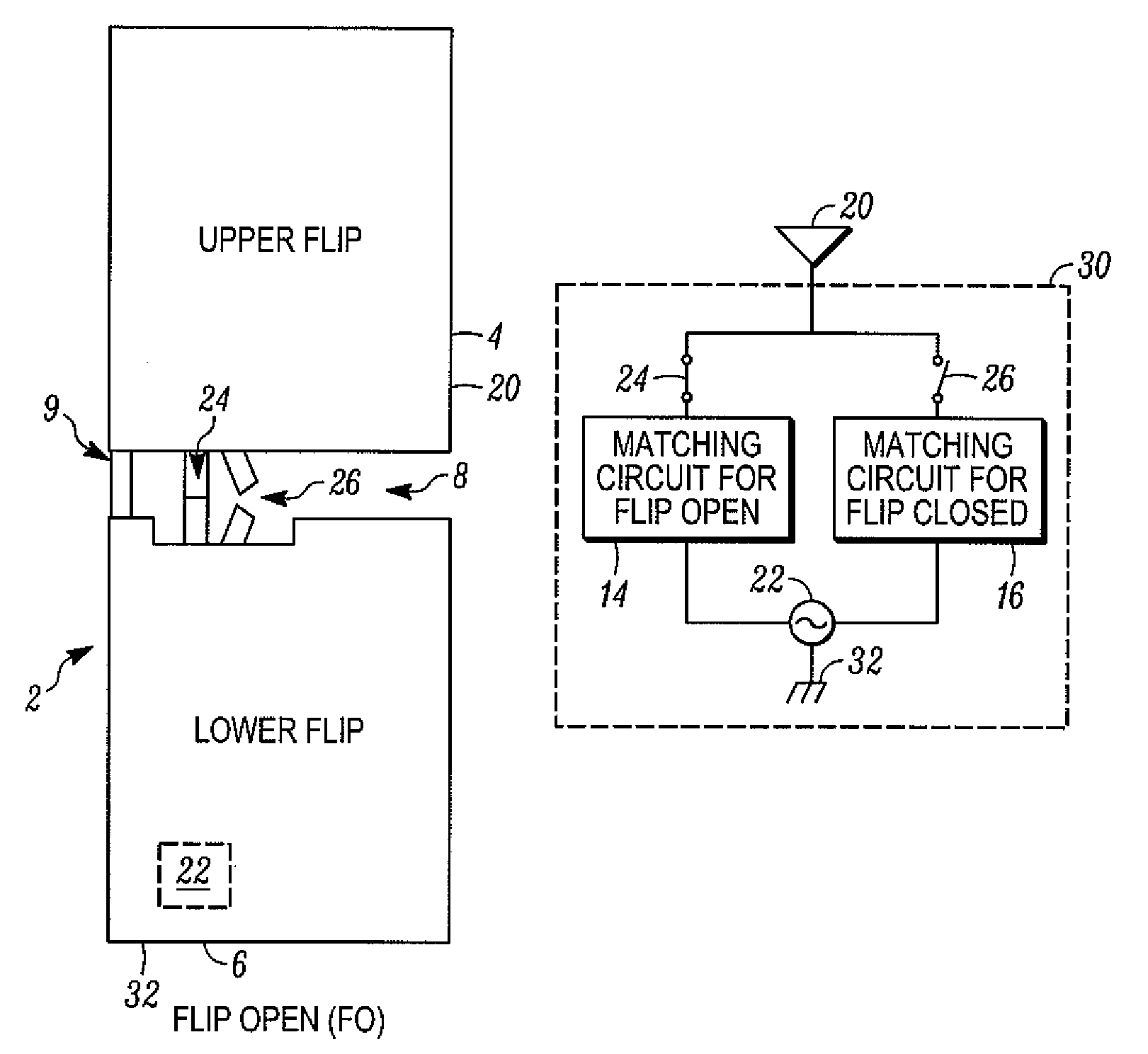
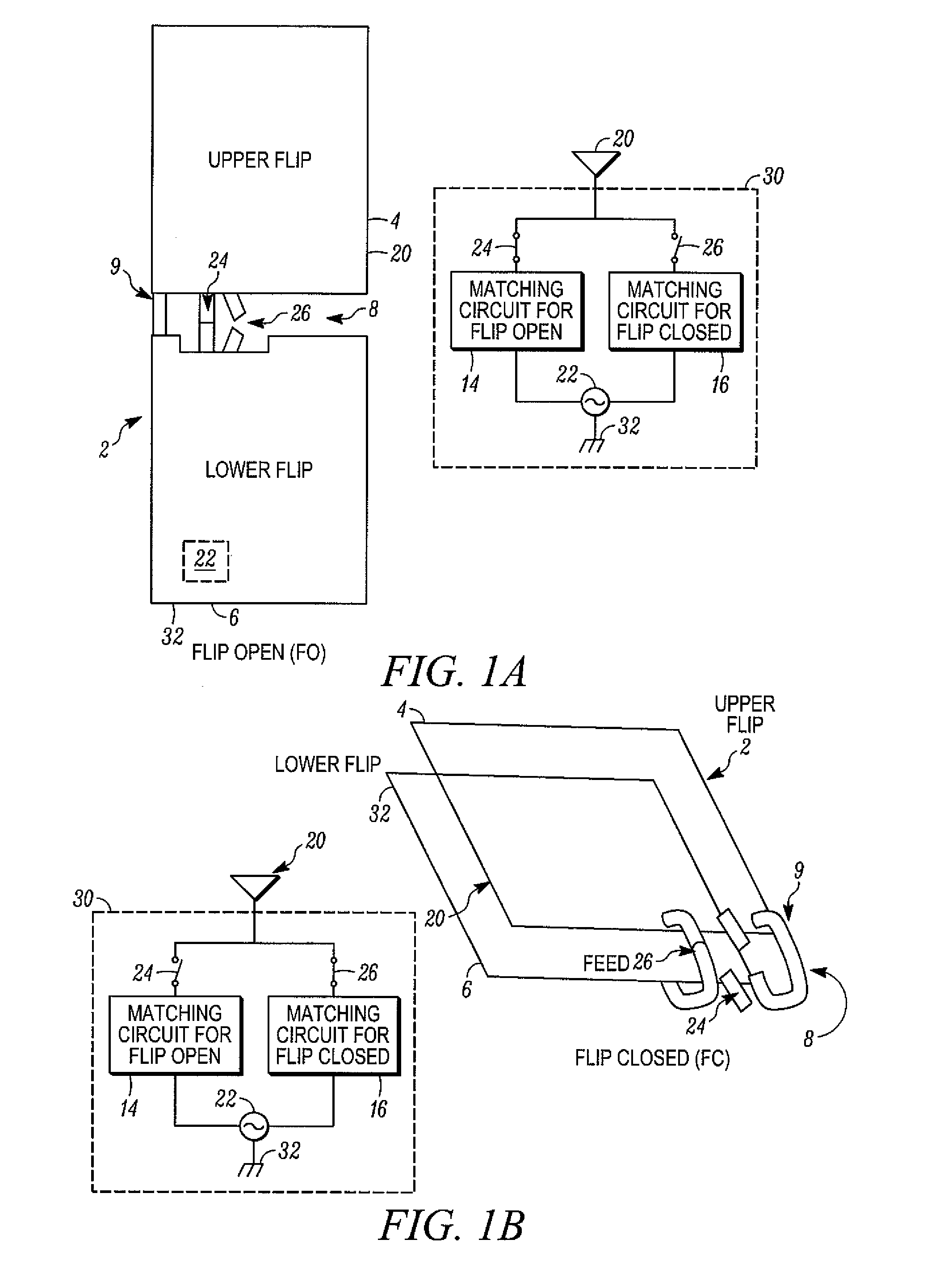
[0016]Referring to FIGS. 1A and 1B, an exemplary wireless communication device is shown that in the present embodiment, is a cellular telephone 2. Further as shown, the cellular telephone 2 is a clamshell-type phone having an upper flip section 4 and a lower flip section 6 that are coupled together in a hinged or rotatable manner by way of a hinge or similar mechanism, which in the present embodiment is shown as a hinge 8. The hinge 8 is capable of not only securing the flip sections 4, 6 together in a hinged or rotatable manner, but also is capable of serving as a channel (or multiple channels) through which wires or other connections can pass between the flip sections, allowing for the communication of signals, information and / or power between the flip sections and also serving as a ground connection between the flip sections. In FIGS. 1A and 1B such channels within the hinge 8 are represented by flex connections 9.

[0017]More particularly, FIG. 1A shows the cellular telephone 2 to...


PUM


Abstract

An improved wireless communication device, such as a clamshell-type cellular telephone, and related method of operation are disclosed. In at least some embodiments, the wireless communication device includes a first structure and a second structure that is hingedly coupled to the first structure, where at least a part of at least one of the first and second structures is capable of operating as an antenna. The device further includes an electrical circuit at least partially governing operation of the antenna, where the electrical circuit is supported at least indirectly by at least one of the first and second structures. At least one electrical characteristic of the electrical circuit varies depending upon a relative positioning of the first structure with respect to the second structure.

Description

FIELD OF THE INVENTION[0001]The present invention relates to devices that employ antennas, and more particularly relates to devices that are capable of wireless communications, for example, cellular telephones.BACKGROUND OF THE INVENTION[0002]Wireless communication devices such as cellular telephones, pagers, personal digital assistants, other handheld devices, laptop / notebook personal computers, and other devices are ubiquitous in the modern world. There continues to be an incentive to design these wireless communication devices so that the devices are smaller and more lightweight, so as to improve their portability as well as to achieve other goals (e.g., to reduce power consumption). Notwithstanding the desire for size reductions, it is also desired that the devices be capable of more and more functions and applications (e.g., UPS, WiFi, WiMAX, Bluetooth, Diversity, MediaFLO, DVB-H, etc.). Consequently, the increasingly limited physical volume or “real estate” available within su...

Claims


Application Information

Patent Timeline
Patent Type & Authority Applications(United States)
IPC IPC(8): H01Q1/24
CPCH01Q1/243H01Q1/084
Inventor ABDUL-GAFFOOR, MOHAMMED R.ABEDIN, FAISALPATEL, PRASHANT B.
Owner MOTOROLA INC
Why Eureka
Try Eureka