Mixing Syringe

a technology of mixing syringe and syringe, which is applied in the field of medical science, can solve the problems of inconvenient shaking of the syringe used for injection, unsuitable for mixing pre-mixed solution, and unsuitable for percutaneous procedures, and achieve the effect of eliminating any unused volum

Inactive Publication Date: 2016-04-07
GELBART DANIEL
View PDF1 Cites 2 Cited by
  • Summary
  • Abstract
  • Description
  • Claims
  • Application Information

AI Technical Summary

Benefits of technology

[0010]A perforated separator compartment or liquid permeable bag is attached to the input port in a regular syringe. The perforated compartment only allows liquids to exit the compartment into the main chamber of the syringe, restricting solid particles to the near proximity of the input port of the syringe. When the plunger of the syringe is pressed, the saline solution emerges from holes into the compartment, stirring up the settled particles. As the ejection continues, the compartment is compressed towards the input port by the plunger in order to eliminate any unused volume.

Problems solved by technology

Such particles tend to settle very quickly out of the solution as they are heavier than water, causing an uneven concentration of particles during the injection.
It is inconvenient to keep shaking the syringe used for injection, as the whole process is performed in a few seconds and the doctor has to concentrate on injecting the correct amount.
They are not designed to stir up a pre-mixed solution.
Prior art syringes designed to stir-up embolization mixtures, such as disclosed in US2009 / 0247985, are needlessly complex.
Also, many of the prior art mixing syringes are not designed to be filled with the pre-mixed solution just before use.

Method used


Image

  • Mixing Syringe
  • Mixing Syringe
  • Mixing Syringe

Examples


Embodiment Construction

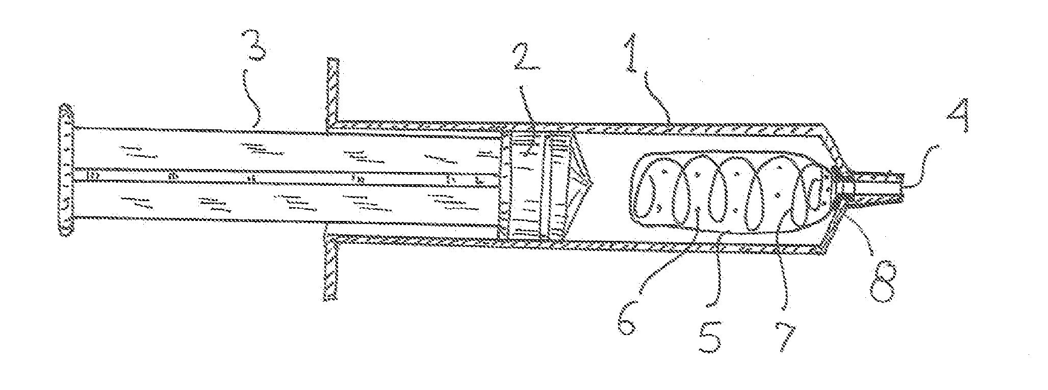
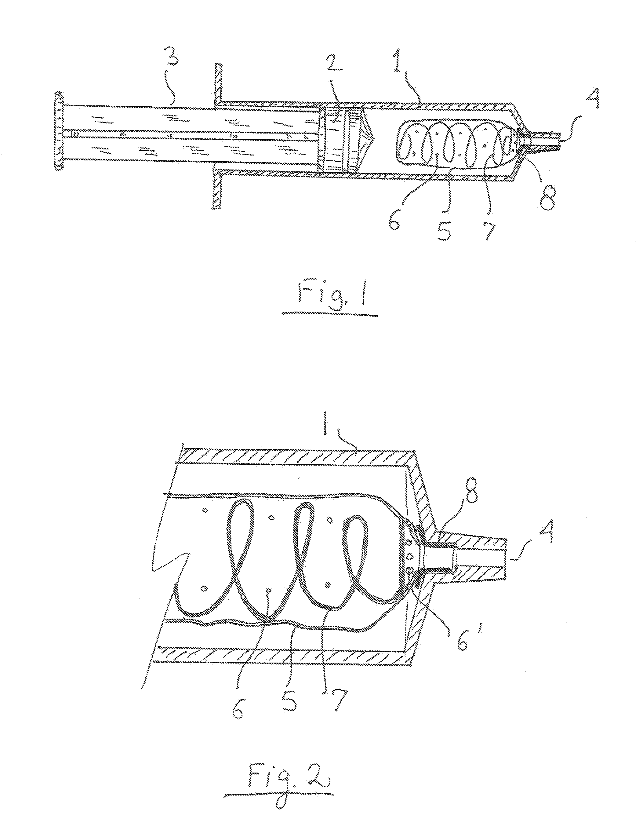
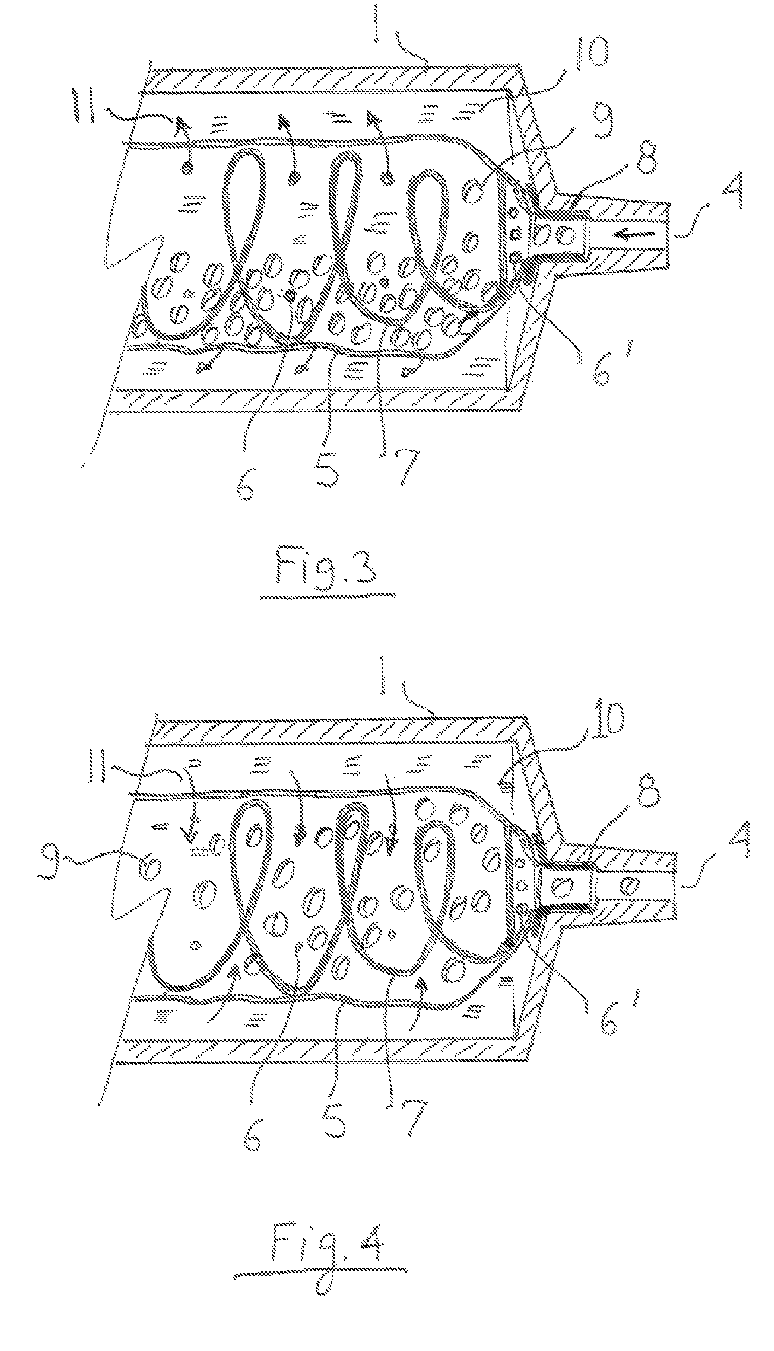
[0016]Referring to FIG. 1 a standard disposable syringe typically comprises of a body 1, plunger 3 incorporating seal 2 and an output port 4, typically a tapered Luer fitting. A perforated bag or compartment 5 is added inside body 1. The bag is connected to the output port either directly (e.g. by adhesive bonding) or held in place by insert 8. A structural reinforcement feature 7 prevents the bag from collapsing. The preferred embodiment of this device uses a spring as a structural reinforcement feature. Spring 7 can be replaced by a reinforcing structure in the bag wall such as corrugations, turning the bag into a bellows. The bag is perforated in several places with holes or slots 6 smaller than the particles the bag contains. To make syringe work at low feed rates, a small number of small diameter perforations are used, to achieve reasonable jet velocity. When the syringe is filled with a mixture of particles in a liquid, typically saline solution, the mixture is sucked in via p...


PUM


Abstract

A perforated separator compartment or liquid permeable bag is attached to the input port in a regular syringe. The perforated compartment only allows liquids to exit the compartment into the main chamber of the syringe, restricting solid particles to the near proximity of the input port of the syringe. When the plunger of the syringe is pressed, the saline solution emerges from holes into the compartment, stirring up the settled particles. As the ejection continues, the compartment is compressed towards the input port by the plunger in order to eliminate any unused volume.

Description

FIELD OF THE INVENTION [0001]The invention is in the medical field, and is particularly useful in percutaneous procedures such as embolization.BACKGROUND OF THE INVENTION[0002]In certain medical procedures, such as blood vessel embolization, it is desired to inject particles into the body. The procedure is a minimally invasive alternative to surgery. The purpose of embolization is to prevent blood flow to an area of the body, which effectively can shrink a fibroid, such as a uterine fibroid. It can also shrink a tumour or block an aneurysm. It is typically done by injecting blocking particles into a blood vessel.[0003]The procedure is carried out as an endovascular procedure by a radiologist in an interventional suite. It is common for most patients to have the treatment carried out with little or no sedation, although this depends largely on the organ to be embolized.[0004]Access to the organ in question is acquired by means of a guidewire and catheter. The position of the correct ...

Claims


Application Information

Patent Timeline
Patent Type & Authority Applications(United States)
IPC IPC(8): A61B17/12A61M5/24A61M5/28
CPCA61B17/12186A61M5/2448A61M5/284A61B2017/00495A61M5/19A61M5/3134A61M5/31596
Inventor GELBART, DANIEL
Owner GELBART DANIEL
Why Eureka
Try Eureka